Electrical connector device of LED light

Active Publication Date: 2017-09-28
XIAMEN ECO LIGHTING CO LTD
9 Cites 4 Cited by

AI-Extracted Technical Summary

Problems solved by technology

By this way, the resistance portion may provide the counterforce for the elastic clipp...

Method used

[0017]When assembled, the other end of the input terminal (10) elastically touches one end of the elastic resistance portion (22) and the resistance portion (23) touches the other end of the resistance portion. In our embodiment, the other end of the input terminal (10) elastically touches the top of the elastic clipping portion (22), and the resistance portion (23) touches the middle of the elastic clipping portion (22). Therefore, the input terminal (10) separates from the resistance portion (23) may effectively limit the deform range of the elastic clipping portion (22). In conclusion, this electrical connector of LED light includes an input terminal (10) and an output terminal (20). The driver board (40), the input terminal...

Benefits of technology

[0005]Comparing with the existed technology, this electrical connector of LED light includes an input terminal and an output terminal. The driver board, the input terminal, the output terminal and the light source board connect one by one. The output terminal specially sets an elastic clipping portion, and a resistance portion and when assembled, the other end of the input terminal elastically touches o...

Abstract

An electrical connector device for electrically connecting a light source board and a driver board of an LED light. The electrical connector device includes an input terminal and an output terminal, one end of input terminal is fixed on the driver board of the LED light and electrically connected to the driver board. The output terminal includes a conductive terminal, an elastic clipping portion, and a resistance portion, the conductive terminal includes a conductive pin, the conductive pin is fixed on the light source board and electrically connected to the light source board, the elastic clipping portion and the resistance portion are placed on the conductive terminal, and when assembled, the other end of the input terminal elastically touches one end of the elastic resistance portion and the resistance portion touches the other end of the resistance portion. The electrical connector of LED light owns the advantages of simple structure and high reliability.

Application Domain

Electric circuit arrangementsCoupling contact members +2

Technology Topic

EngineeringLight source +4

Image

  • Electrical connector device of LED light
  • Electrical connector device of LED light
  • Electrical connector device of LED light

Examples

  • Experimental program(1)

Example

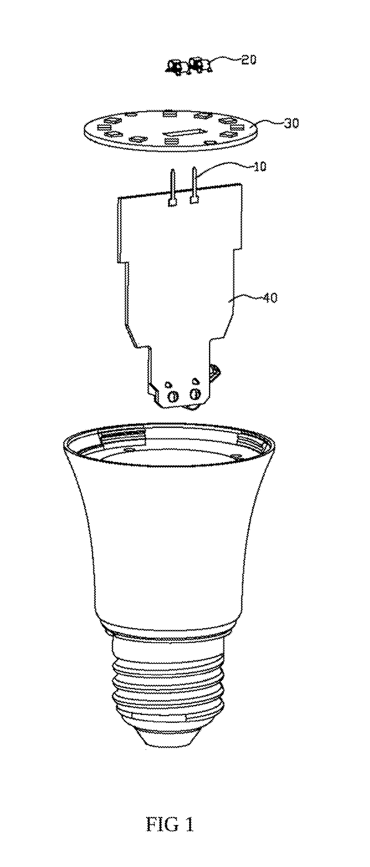
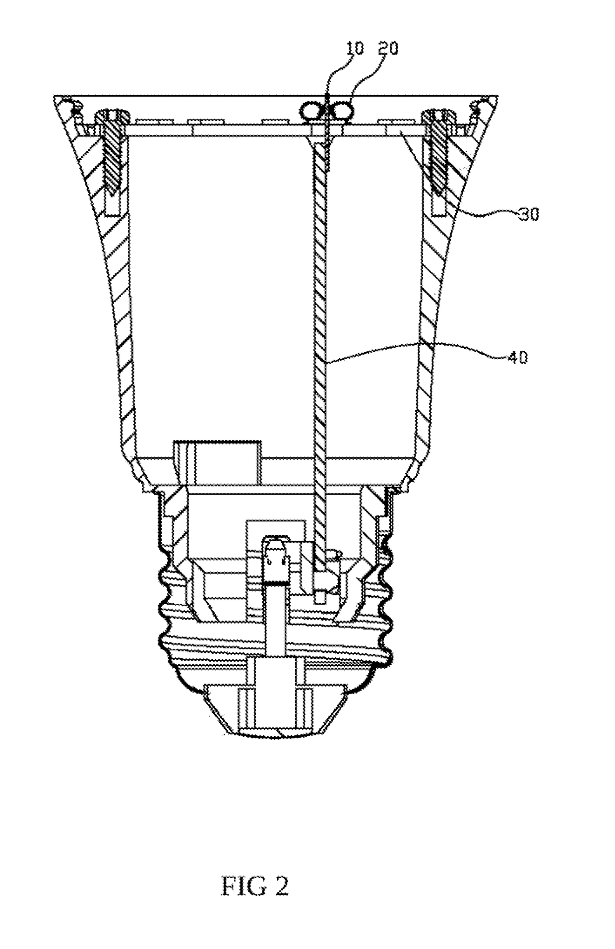
[0012]FIG. 1 is the first embodiment stereoscopic decomposition drawing for the present invention, an electronic connector of an LED light. The electrical connector device connects a light source board (30) and a driver board (40) of an LED light electrically. The electrical connector device includes an input terminal (10) and an output terminal (20), one end of input terminal (10) is fixed on the driver board (40) of the LED light and electrically connected to the driver board (40).
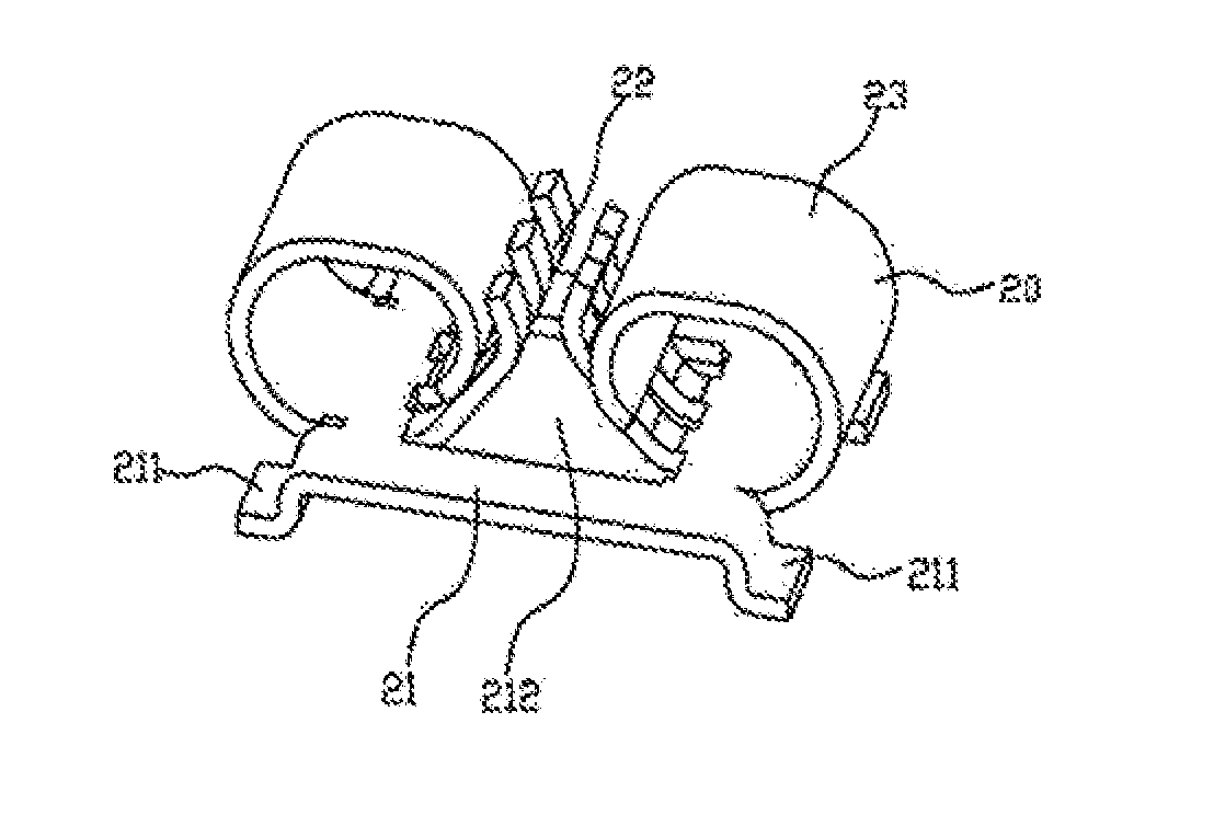
[0013]Based on FIG. 3, the output terminal (20) includes a conductive terminal (21), an elastic clipping portion (22), and a resistance portion (23). The elastic clipping portion (22) and the resistance portion (23) are placed on the conductive terminal (21), in this implementation, the elastic clipping portion (22) and the resistance portion (23) are placed together on the conductive terminal (21) and the conductive terminal (21) is made of metal.
[0014]Based on FIG. 2 to FIG. 4, the conductive terminal (21) includes a conductive pin (211) , usually the conductive terminal (21) through the conductive pin (211) is fixed on the light source board (30) and electrically connected to the light source board (30).
[0015]The bottom of the elastic clipping portion (22) is connected to the conductive terminal (21), and the top of the elastic clipping portion (22) is bent with a tilt angle toward the direction away from the conductive terminal (21). In our embodiment, the electrical connector includes two elastic clipping portions (22), the two elastic clipping portions are disposed face to face and form a China character, ‘ ’, structure, and the elastic clipping portions separately elastically touch two side walls of the input terminal (10). The conductive terminal (21) has a through hole (212), the elastic clipping portions (22) are symmetrically disposed at two sides of the through hole (212), the input terminal (10) is through the through hole (212) and electrically connected to the elastic clipping portions (22).
[0016]In this embodiment, the resistance portion (23) is a ‘ ’ shape bending structure, the resistance portion (23) is fixed on the conductive terminal (21), and the other end of the resistance portion (23) touches the elastic clipping portion (22). There is an opening in each elastic clipping portion (22) so that each elastic clipping portion (22) forms a comb structure. These elastic clipping portions'(22) comb structures with cross set so that rise the elastic clipping portion's(22) flexibility in one hand. On the other hand, the comb structure make the input terminal connect with the elastic clipping portion (22) own much electricity to touch and rise the possibility of electronic connection.
[0017]When assembled, the other end of the input terminal (10) elastically touches one end of the elastic resistance portion (22) and the resistance portion (23) touches the other end of the resistance portion. In our embodiment, the other end of the input terminal (10) elastically touches the top of the elastic clipping portion (22), and the resistance portion (23) touches the middle of the elastic clipping portion (22). Therefore, the input terminal (10) separates from the resistance portion (23) may effectively limit the deform range of the elastic clipping portion (22). In conclusion, this electrical connector of LED light includes an input terminal (10) and an output terminal (20). The driver board (40), the input terminal (10), the output terminal (20)and the light source board (30) connect one by one. The output terminal specially sets an elastic clipping portion (22), and a resistance portion (23) and when assembled, the other end of the input terminal (10) elastically touches one end of the elastic resistance portion (22) and the resistance portion (23) touches the other end of the resistance portion (23). By this way, the resistance portion (23) may provide the counterforce for the elastic clipping portion (22) to make the elastic clipping portion (22) become tighter and difficult to move when connected to the input terminal (10). Furthermore, the electrical connector of LED light owns the advantages of simple structure and high reliability.
[0018]Certainly, the resistance portion is capable of a rigid structure, one end of the resistance portion (23) is fixed on the conductive terminal (21), and the other end of the resistance portion (23) touches the middle of the elastic clipping portion (22). By this way, it may have the same effect on limiting the deform of the elastic clipping portion (22).
[0019]The statement above just for the better embodiment, not for limiting the present invention. All the modification, equal to any change and improvement that are based on the present invention's spirit and principle, may be protected in the present invention protection range.

PUM

no PUM

Description & Claims & Application Information

We can also present the details of the Description, Claims and Application information to help users get a comprehensive understanding of the technical details of the patent, such as background art, summary of invention, brief description of drawings, description of embodiments, and other original content. On the other hand, users can also determine the specific scope of protection of the technology through the list of claims; as well as understand the changes in the life cycle of the technology with the presentation of the patent timeline. Login to view more.

Similar technology patents

Photoelectric sensor for position of sun

InactiveCN101650173AEffective tracking range expandedSimple structure
Owner:WUHAN UNIV OF TECH

Magnetic cooling apparatus and control method thereof

ActiveUS20130180263A1simple structure
Owner:SAMSUNG ELECTRONICS CO LTD

Dual-Drivetrain of Power-Assist Vehicle

InactiveUS20100181130A1enhance uphill momentumsimple structure
Owner:CHOU WEN CHENG

Classification and recommendation of technical efficacy words

Why Eureka
Try Eureka