
Physiological sensor controller, physiological sensor system and non-transitory computer readable medium

Active Publication Date: 2017-09-28
FUJIFILM CORP
View PDF11 Cites 4 Cited by
  • Summary
  • Abstract
  • Description
  • Claims
  • Application Information

AI Technical Summary

Benefits of technology

The present invention provides a physiological sensor controller that makes it simple to verify the combination of a physiological sensor and a patient without being complicated. This invention only outputs information to encourage a retry for verification only when required. This simplifies the process of verifying the combination between the sensor and patient.

Problems solved by technology

In case the physiological sensor is removed, there occurs abnormality in receptivity of the measurement signal at the physiological sensor controller.
A reason for the abnormality in the receptivity can be temporary removal of the physiological sensor at the time of bathing, and also can be an error in delivering the physiological sensor of a certain type to the patient.
An example of the abnormality in the receptivity of the measurement signal is instantaneous interruption of a communication path at a short time in addition to that due to the removal of the physiological sensor.
The use of the retry for verification is not favorable on the side of the patient because of complexity.
However, the verification requires additional steps of operation because of use of the verification image.

Method used


Image

  • Physiological sensor controller, physiological sensor system and non-transitory computer readable medium
  • Physiological sensor controller, physiological sensor system and non-transitory computer readable medium
  • Physiological sensor controller, physiological sensor system and non-transitory computer readable medium

Examples


first embodiment

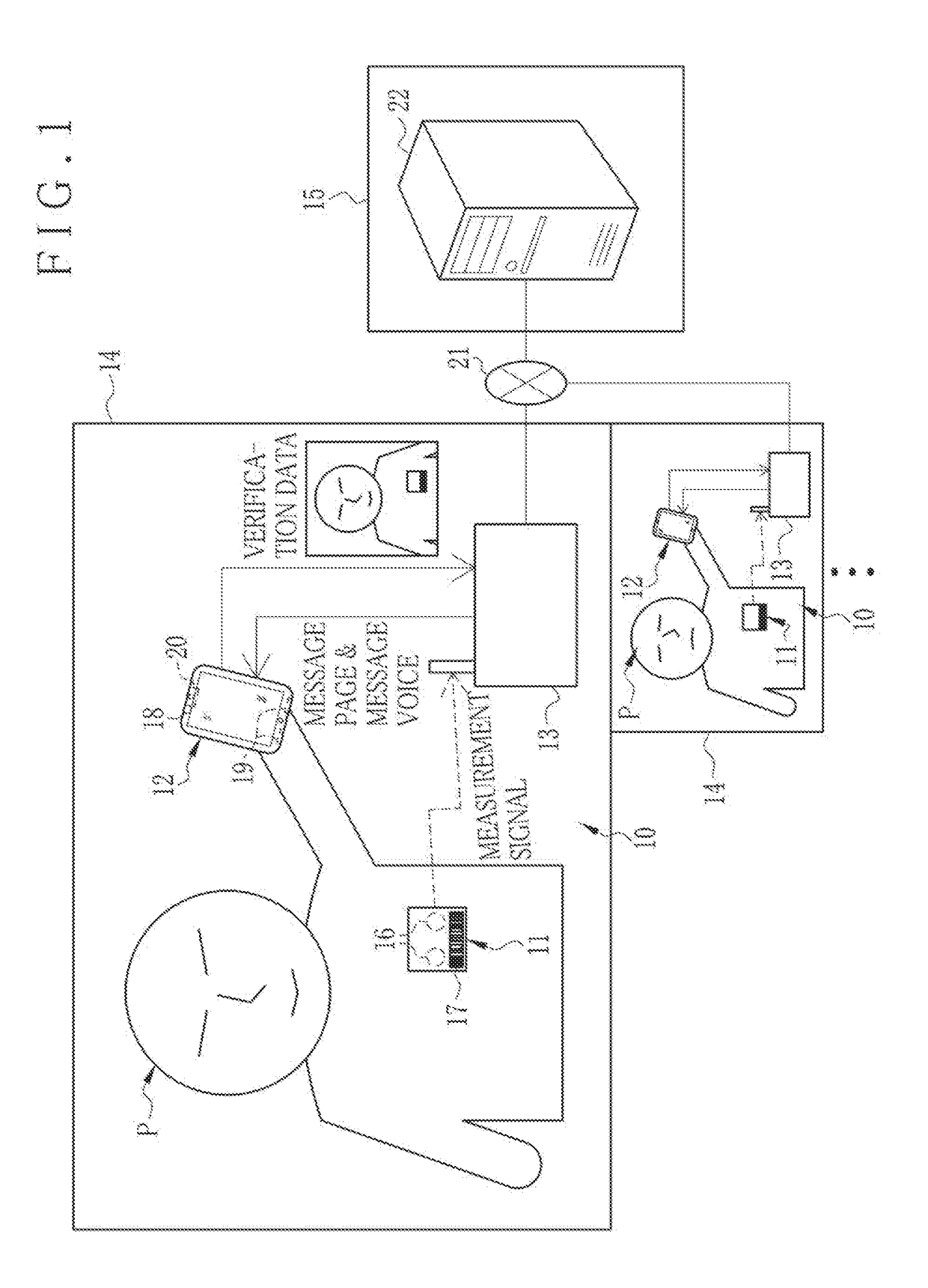
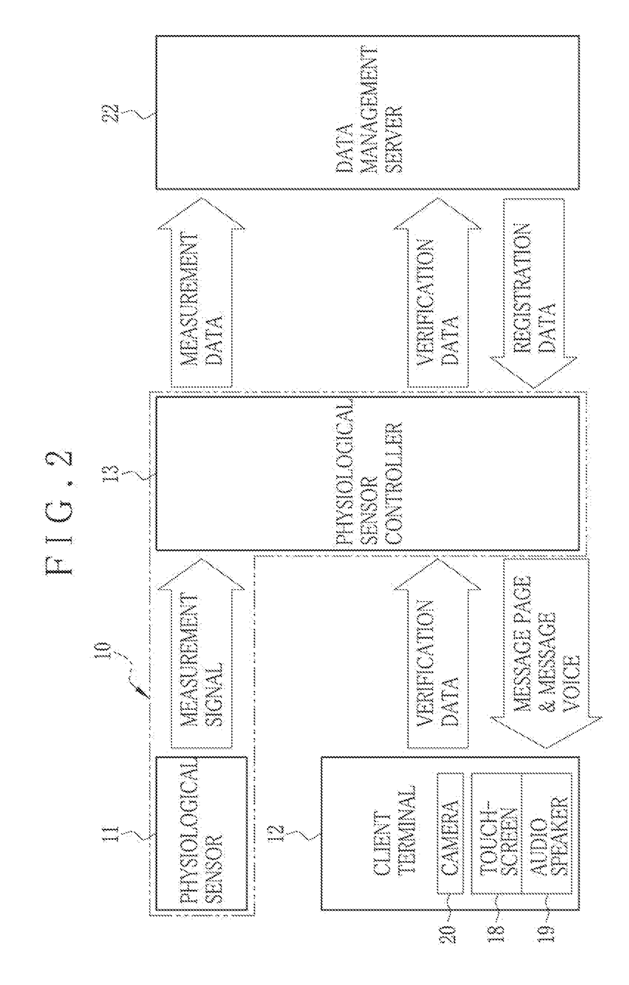
[0077]In FIG. 1, a physiological sensor system 10 (patient monitoring system) includes a physiological sensor 11 or ECG sensor (physiological monitoring device), and a physiological sensor controller 13 (physiological monitoring apparatus), and is installed in a patient's home 14 of a patient P (examinee) who uses a client terminal device 12. The patient P visits a medical facility 15 or hospital periodically as an out-patient. In the home 14, the patient P positions the physiological sensor 11 delivered by the medical facility 15 on his or her body.

[0078]The physiological sensor 11 measures physiological information of the patient P, and outputs a measurement signal at a predetermined sampling period. In the embodiment, a disease of the patient P is a heart disease. The physiological sensor 11 is an ECG sensor in a form of a regular square. The physiological information measured by the physiological sensor 11 is an ECG waveform. A measurement signal output by the physiological sens...

second embodiment

[0134]In the first embodiment, the requirement of retry for verification is checked according to the time duration TAb of the state of detecting abnormality in the receptivity of the measurement signal. In contrast, the requirement of retry for verification is checked in FIGS. 16-18 according to a result of comparison between the measurement signal before detecting the abnormality in the receptivity and a measurement signal after recovery of the receptivity to the normality.

[0135]In FIGS. 16-18, reference time TTh2 is preset in addition to the reference time TTh1 of the first embodiment with a larger length than the reference time TTh1. For example, the reference time TTh2 is two times as long as the reference time TTh1. The receiver 52 inputs a measurement signal to the checker 54, which has a memory for temporarily storing the measurement signal of plural times of the sampling.

[0136]At first, assuming that the time duration TAb of the state of detecting abnormality in the receptiv...

third embodiment

[0143]In general, a correct sensor position where the physiological sensor 11 should be mounted on the patient body is predetermined. The sensor position may differ between patients P for the reason of differences in the size of the patient body. Also, plural sensor positions should be predetermined in combination with plural diseases or health problems of the patients P even in the use of the same physiological sensor 11. Should the physiological sensor 11 be positioned in an incorrect position, reliability of physiological information from the physiological sensor 11 may be lower medically. Also, the detector 53 may detect abnormality of the receptivity of the measurement signal due to the incorrectness of the sensor position, so that the retry for verification may be required.

[0144]The sensor position of the physiological sensor 11 can be recognized in the verification image. In FIGS. 19-26, the sensor position of the physiological sensor 11 is detected by use of the verification...


PUM


Abstract

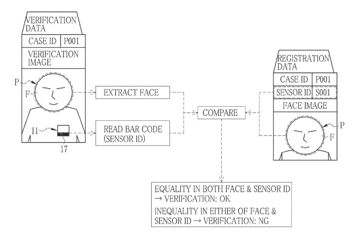
A physiological sensor controller controls a physiological sensor (or ECG sensor), positioned on a patient body, for measuring physiological information (or ECG waveform) of the patient body to output a measurement signal. An acquisition device acquires a verification image containing portions of identification information of the physiological sensor and a face of the patient body. A verifier performs verification of acceptability in a combination of the physiological sensor and the patient body according to the verification image. A receiver receives the measurement signal. A detector detects normality or abnormality of receptivity of the measurement signal. A checker operates assuming that the detector determines the abnormality of the receptivity, and checks whether a retry for the verification in the verifier is required or not. An output device operates assuming that the checker determines requirement of the retry for the verification, and outputs information of encouraging the retry for the verification.

Description

CROSS-REFERENCE TO RELATED APPLICATION[0001]This application claims priority under 35 USC 119 from Japanese Patent Application No. 2016-058404, filed 23 Mar. 2016, the disclosure of which is incorporated by reference herein.BACKGROUND OF THE INVENTION[0002]1. Field of the Invention[0003]The present invention relates to a physiological sensor controller, a physiological sensor system and a non-transitory computer readable medium. More particularly, the present invention relates to a physiological sensor controller in which a combination between a physiological sensor and a patient can be verified in a facilitated manner without complexity, a physiological sensor system and a non-transitory computer readable medium.[0004]2. Description Related to the Prior Art[0005]In the field of medical instruments, a physiological sensor (physiological monitoring device) is used and positioned on a body of a patient (examinee) of home care at his or her home. A doctor (or other medical professional...

Claims


Application Information

Patent Timeline
IPC IPC(8): G06K9/00A61B5/0402G06F19/00A61B5/00G16H40/67
CPCG06K9/00892A61B5/0002A61B5/0402G06K2009/00939G06K9/00288G06F19/3418A61B5/0022A61B5/1176A61B2562/08G16H40/67A61B5/318G06V40/172G06V40/70G06V40/15G16H40/40G06V20/20
Inventor KUDO, YUYA
Owner FUJIFILM CORP
Learn More