Magnetic circuit component

a technology of magnetic circuit and component, applied in the direction of coils, transformers/inductance details, inorganic material magnetism, etc., can solve the problems of significant deterioration in the efficiency of switching power supply, increase in the alternating current resistance of coils, loss generation, etc., to reduce the density of magnetic flux, reduce the quantity of magnetic materials, and reduce the effect of eddy current loss

Active Publication Date: 2017-09-28
DENSO CORP
View PDF8 Cites 4 Cited by
  • Summary
  • Abstract
  • Description
  • Claims
  • Application Information

AI Technical Summary

Benefits of technology

[0013]By adopting the above configuration, a magnetic material section is formed over a coil surface where a magnetic flux concentrates in the state of a coil formed by winding a conductor and hence it is possible to attempt to: reduce the density of the magnetic flux over the coil surface; and reduce an eddy-current loss. As a result further, it is possible to reduce the quantity of a magnetic material not contributing to the reduction of a magnetic flux density in comparison with the case of constituting the conductor of a coil with a magnetic plated wire, in other words, it is possible to obtain the effect of reducing a magnetic flux density more effectively when the quantity of a magnetic material is identical by arranging a not-functioning magnetic material over the surface of a coil. This is synonymous with the increase of a sectional area with which a magnetic flux interlinks and, when an electricity is applied to a conductive wire so as to generate an identical magnetic flux, it is possible to reduce the magnetic flux density in the interior of the magnetic material section comprising a magnetic material to the extent of the increase of the sectional area. As a result, the same eddy-current loss reduction effect as magnetic plating is obtained and at the same time magnetic saturation that emerges as the problem caused by a magnetic plated wire can be restrained without increasing the quantity of a magnetic material at an extra cost.

Problems solved by technology

Eddy-current loss caused by skin effect, proximity effect, or leakage flux in a copper wire or a coil increases with the increase of frequency and thus a problem here is that the alternating-current resistance of a coil increases.
When an alternating-current resistance increases, loss generated in a coil increases and hence a significant deterioration in the efficiency of a switching power supply is concerned.
Consequently, a challenge on the occasion of higher frequency is to restrain an alternating-current resistance caused by leakage flux from increasing.
In addition, in a reactor or a transformer for a switching power supply, a magnetic core (core) is arranged next to a coil in many cases and hence loss caused by a leakage flux from a magnetic core is likely to be generated.

Method used


Image

  • Magnetic circuit component
  • Magnetic circuit component
  • Magnetic circuit component

Examples


first embodiment

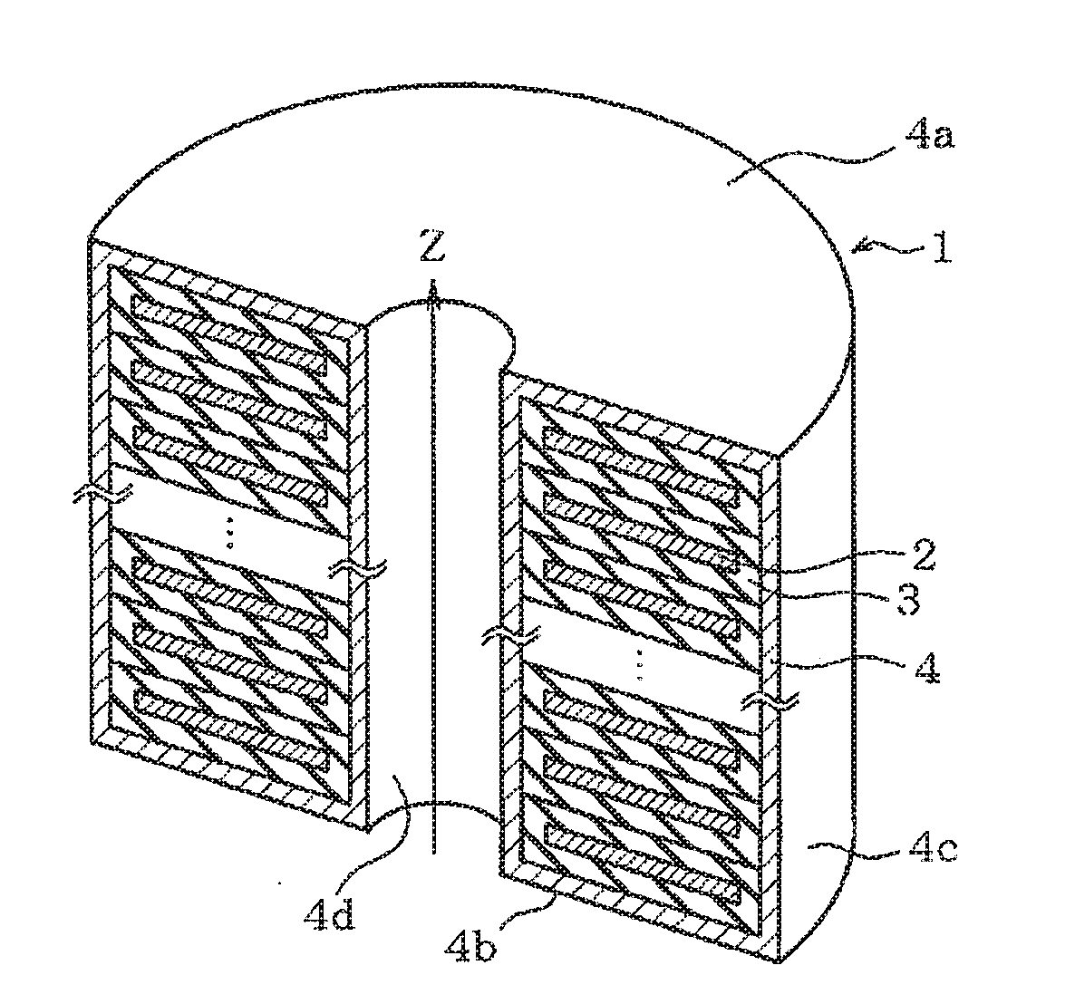
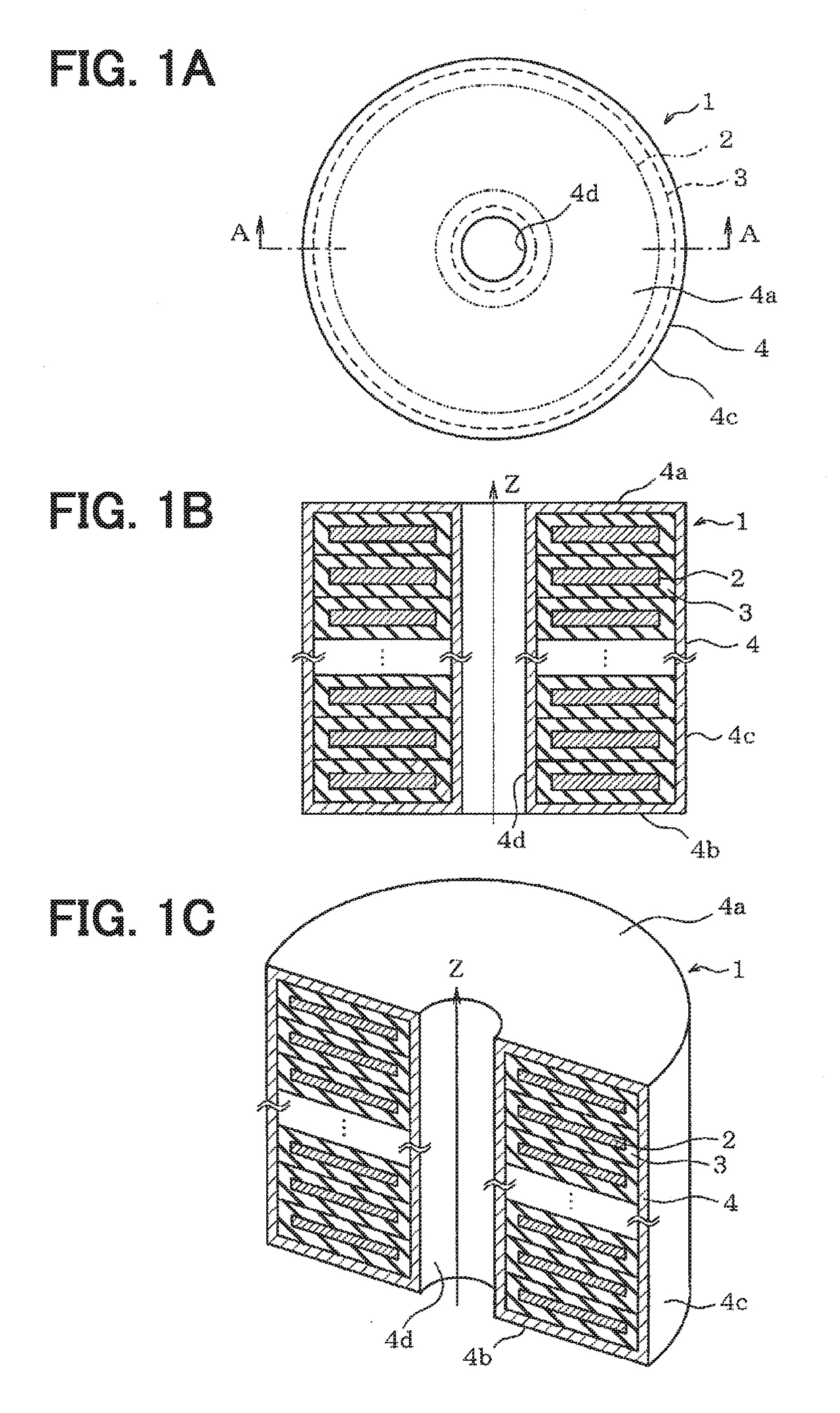
[0049]A first embodiment is explained hereunder in reference to FIGS. 1A to 3B. FIGS. 1A to 1C illustrate a whole configuration and an outer appearance of a coil 1 incorporated in a reactor or a transformer. FIG. 1A is a plan view of the coil 1 viewed from the top side and FIG. 1B is a sectional view taken on line A-A in FIG. 1A. Then FIG. 1C is an external perspective view in a cut state.

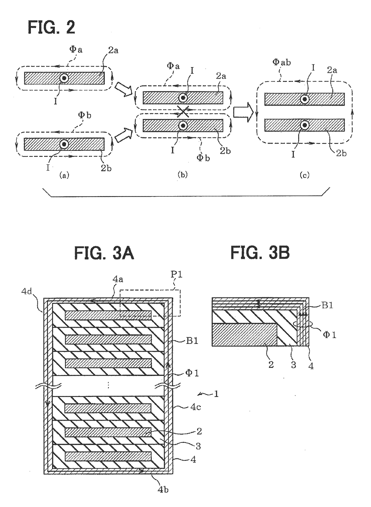
[0050]The coil 1 is configured by winding a rectangular conductor 2 having a cross section of a flat rectangle and the surface of the conductor 2 as a winding wire is covered with an insulation film 3. The insulation film 3 has an identical thickness as a whole and has a thickness in the range of 10 to 100 μm for example. The coil 1 is formed in the state of winding the conductor 2 around an axis z and stacking the flat faces in the direction of the axis z. The conductor 2 in the coil 1 is in the state of being partitioned by the insulation film 3 between vertically adjacent two conductors 2. Magne...

second embodiment

[0066]FIGS. 4A to 5C illustrate a second embodiment. In the embodiment, a coil 11 is configured to have a magnetic material section 14 (14a and 14b): split so as to expose parts of an insulation film 13 over the surface of a wound conductor 12; and arranged in place of the magnetic material section 4 according to the first embodiment.

[0067]As illustrated in FIGS. 4A to 4C, a coil 11 is formed by winding a conductor 12 covered with an insulation film 13 similarly to the first embodiment. A cap-shaped magnetic material section 14a covering a top face and parts of an outside face and an inside face is installed and a cap-shaped magnetic material section 14b covering a bottom face and parts of an outside face and an inside face is installed, those faces constituting the surface of the coil 11. More specifically, the magnetic material sections 14a and 14b are installed at the parts corresponding to the start and the end of the winding of the conductor 12 in the coil 11 respectively. The ...

third embodiment

[0080]FIGS. 6A to 7B illustrate a third embodiment. In the embodiment, a coil 21 is configured to have a magnetic material section 24 (24a to 24d) split into four sections so as to expose parts of the surface of an insulation film 23 over a wound conductor 22 and arranged.

[0081]As illustrated in FIGS. 6A to 6C, a coil 21 is formed by winding a conductor 22 covered with an insulation film 23 similarly to the first embodiment. A magnetic material section 24a covering upper outside-and-top faces, a magnetic material section 24b covering lower outside-and-bottom faces, a magnetic material section 24c covering upper inside-and-top faces, and a magnetic material section 24d covering lower inside-and-bottom faces, those faces constituting the surface of the coil 21, are installed respectively. The magnetic material sections 24a to 24d are formed by attaching tabular magnetic materials comprising a soft magnetic material to the coil 21 respectively. The thicknesses of the magnetic material ...


PUM

PropertyMeasurementUnit
thicknessaaaaaaaaaa
thicknessaaaaaaaaaa
thicknessesaaaaaaaaaa

Abstract

A magnetic circuit component includes a magnetic core and a coil formed by winding a conductor around the magnetic core. The magnetic circuit component includes a magnetic material section that is formed from a soft magnetic material, and that covers a part of a surface of the coil or the entire surface of the coil and is disposed away from the magnetic core.

Description

CROSS REFERENCE TO RELATED APPLICATION[0001]This application is based on Japanese Patent Application No. 2014-140436 filed on Jul. 8, 2014, the disclosure of which is incorporated herein by reference.TECHNICAL FIELD[0002]This disclosure relates to a magnetic circuit component.BACKGROUND ART[0003]In recent years, the downsizing of a magnetic circuit component such as a reactor or a transformer used in a power supply circuit is urged strongly with an increasing demand for the downsizing of a switching power supply. In a switching power supply, as a method of materializing downsizing, higher frequency is attempted in some cases. Eddy-current loss caused by skin effect, proximity effect, or leakage flux in a copper wire or a coil increases with the increase of frequency and thus a problem here is that the alternating-current resistance of a coil increases. When an alternating-current resistance increases, loss generated in a coil increases and hence a significant deterioration in the ef...

Claims


Application Information

Patent Timeline
Patent Type & Authority Applications(United States)
IPC IPC(8): H01F1/12H01F5/00H01F5/04H01F3/14H01F5/06
CPCH01F1/12H01F3/14H01F2003/106H01F5/04H01F5/003H01F5/06H01F3/10H01F27/325H01F27/346H01F2027/348H01F27/36H01F27/366
Inventor KONDOU, NAOYASAKAMOTO, AKIRAUMETANI, KAZUHIRO
Owner DENSO CORP
Why Eureka
Try Eureka