Ipm rotor

a permanent magnet, rotating technology, applied in the direction of magnetic circuit rotating parts, dynamo-electric machines, magnetic circuit shape/form/construction, etc., can solve the problems of magnets being physically fragile, reluctance to use resonant torque, large generated torque, etc., to reduce the density of magnetic flux and simple structure

Active Publication Date: 2020-01-30
MITSUBISHI ELECTRIC CORP
View PDF0 Cites 2 Cited by
  • Summary
  • Abstract
  • Description
  • Claims
  • Application Information

AI Technical Summary

Benefits of technology

[0014]According to the IPM rotor of the present invention, movement of the magnet in the longitudinal direction in the hole portion is regulated by the protruding portion. Further, the magnet is fixed in the width direction of the hole portion by the spring plate portion. The recessed portion is provided in the bending direction of the spring plate portion. Thus, the recessed portion is filled by the spring plate portion, and hence a gap is not defined. Further, the spring plate portion is provided at a position which does not cause a decrease in magnetic flux density.
[0015]With this, an IPM rotor which is capable of suppressing a decrease in magnetic flux density and holding magnets with a simple structure can be provided.

Problems solved by technology

Further, generated torque is large, and hence reluctance torque can be used.
Further, in some cases, the IPM rotor may rotate at high speed, may suddenly rotate, or may suddenly stop.
In addition, the magnets are physically fragile, that is, are liable to be chipped and cracked.

Method used


Image

  • Ipm rotor
  • Ipm rotor
  • Ipm rotor

Examples


first embodiment

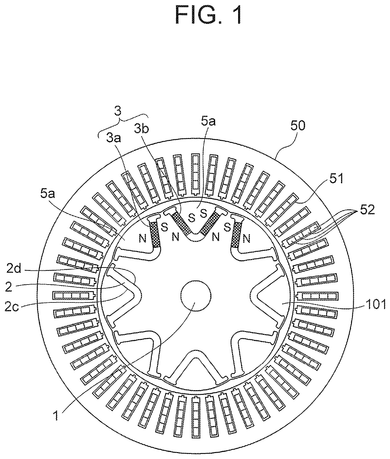
[0030]FIG. 1 is a sectional view for illustrating a motor including an IPM rotor according to a first embodiment of the present invention as seen from a direction of a rotary shaft of the motor. As illustrated in FIG. 1, an IPM rotor 101 is provided around a rotary shaft 1 as a center axis.

[0031]The IPM rotor 101 has eight hole portions 2 each having a V-shape. The hole portion 2 each have outward surfaces 2c on a radially outer side of the IPM rotor and inward surfaces 2d on a radially inner side of the IPM rotor 101. One magnet 3 having a substantially rectangular parallelepiped shape is arranged on both sides of the V-shape of the hole portion 2. The magnets 3 are classified into two cases depending on a direction of a flow of magnetic flux. In one case, a magnet 3a is arranged such that a first core portion 5a as a space defined between both sides of the V-shape is set to be an N-pole. In another case, a magnet 3b is arranged such that a first core portion 5a adjacent to the fir...

second embodiment

[0072]Next, an IPM rotor 102 according to a second embodiment of the present invention is described with reference to FIG. 8 to FIG. 11. The second embodiment differs from the first embodiment in a shape of hole portions in which the the magnets are inserted.

[0073]FIG. 8 is a schematic view for illustrating the IPM rotor 102 according to the second embodiment as seen from a direction of the rotary shaft 1. In the IPM rotor 102, eight hole portions 4 each having a linear shape are formed in an arc direction of the IPM rotor 102 having a substantially circular shape. Magnets 3 to be inserted in the hole portions 4 are arranged such that N-poles and S-poles are alternately arranged along an outer side of the IPM rotor 102. Both ends of each hole portion 4 in the longitudinal direction are widened to form gaps 4a and 4b. The gaps 4a and 4b are flux barrier holes, and intend to suppress a direct flow of the magnetic flux of the magnets 3 adjacent to each other. Further, bridge portions 5...

third embodiment

[0084]Next, an IPM rotor according to a third embodiment of the present invention is described with reference to FIG. 12 and FIG. 13. In the third embodiment, protruding portions, which are configured to restrain movement in a longitudinal direction of a magnet, are arranged in a first core sheet having a spring plate portion.

[0085]In FIG. 12 and FIG. 13, there is given an enlarged illustration of only a portion of a core sheet having a substantially circular shape. Further, in FIG. 12 and FIG. 13, a state, in which the magnet 3 is inserted in each hole portion, is illustrated.

[0086]FIG. 12 is a partial plan view for illustrating a first core sheet 31. The first core sheet 31 has hole portions 31h in an arc direction. Each hole portion 31h has an outward surface 4c on a radially outer side, and an inward surface 4d on a radially inner side, of the first core sheet 31. A spring plate portion 31a is arranged to a central portion 3m of a long side of the magnet 3 in the inward surface ...


PUM


Abstract

According to the present invention, provided is an IPM rotor of the present invention, which includes a plurality of core sheets, having hole portions configured to accommodate magnets and being laminated on one another, and the magnets are inserted in the hole portions. The IPM rotor includes a first core sheet having a spring plate portion provided to the hole portion, and a second core sheet having a recessed portion provided the hole portion. A protruding portion is provided to the hole portion of at least one of the plurality of the laminated core sheets. The protruding portion is provided to at least one of the hole portion of the first core sheet, the hole portion of the second core sheet, or a hole portion of a third core sheet to be further arranged.

Description

TECHNICAL FIELD[0001]The present invention relates to an interior permanent magnet (IPM) rotor including laminated core sheets having permanent magnets embedded therein.BACKGROUND ART[0002]In a rotary electric machine, there are two types of rotors using permanent magnets, specifically, a surface permanent magnet (SPM) rotor and an IPM rotor. The SPM rotor have magnets pasted on a surface of a rotator. The IPM rotor have magnets embedded in a rotator. In the IPM rotor, magnets each having a rectangular parallelepiped shape can be used. Thus, the IPM rotor is more advantageous in terms of mounting and cost as compared to the SPM rotor. Further, generated torque is large, and hence reluctance torque can be used. Thus, employment of IPM rotors are being increased.[0003]With regard to such IPM rotors, there has been known a method of laminating substantially circular core sheets, which have punched hole portions having the same shape as a cross section of the magnet, and then inserting ...

Claims


Application Information

Patent Timeline
Patent Type & Authority Applications(United States)
IPC IPC(8): H02K1/27
CPCH02K1/2766H02K1/276
Inventor AIDA, HIROSHIOKAZAKI, MASAFUMITAKIZAWA, YUJIAKUTSU, SATORUNISHIKAWA, HIDEYAMORI, AKIHIKO
Owner MITSUBISHI ELECTRIC CORP
Why Eureka
Try Eureka