Pneumatic Tire, Tire Wear Information Acquisition System, and Method for Acquiring Wear Information of Pneumatic Tire

a technology of pneumatic tires and wear information, which is applied in the direction of electric/magnetic depth measurement, transportation and packaging, instruments, etc., can solve the problems of unavoidable decrease in magnetic field density or magnetic field strength, and the inability to accurately obtain the degree of wear of the tread portion from the change, so as to achieve the effect of high accuracy and decrease in magnetic flux density

Active Publication Date: 2021-06-10
THE YOKOHAMA RUBBER CO LTD
View PDF11 Cites 1 Cited by
  • Summary
  • Abstract
  • Description
  • Claims
  • Application Information

AI Technical Summary

Benefits of technology

[0030]With the pneumatic tire, the tire wear information acquisition system, and the pneumatic tire wear information acquisition method described above, it is possible to obtain wear information with high accuracy without being affected by a decrease in the magnetic flux density or the magnetic field strength of the magnets due to heat generation of the tread rubber of the pneumatic tire, or a decrease in magnetic flux density or magnetic field strength of the magnets due to changes over time.

Problems solved by technology

The magnetic field (magnetic flux density or magnetic field strength) measured by the above method includes changes in the magnetic field strength (magnetic flux density or magnetic field strength) that accompany the use of a magnetic material over time or due to thermal degradation or the like, so the degree of wear of the tread portion could not be accurately obtained from the change in the measured magnetic field strength (magnetic flux density or magnetic field strength).
In particular, the tread rubber of a pneumatic tire generates heat and becomes high in temperature due to the rolling motion of the pneumatic tire, so a decrease in the magnetic field (magnetic flux density or magnetic field strength) of the magnetic body is unavoidable.

Method used


Image

  • Pneumatic Tire, Tire Wear Information Acquisition System, and Method for Acquiring Wear Information of Pneumatic Tire
  • Pneumatic Tire, Tire Wear Information Acquisition System, and Method for Acquiring Wear Information of Pneumatic Tire
  • Pneumatic Tire, Tire Wear Information Acquisition System, and Method for Acquiring Wear Information of Pneumatic Tire

Examples


Embodiment Construction

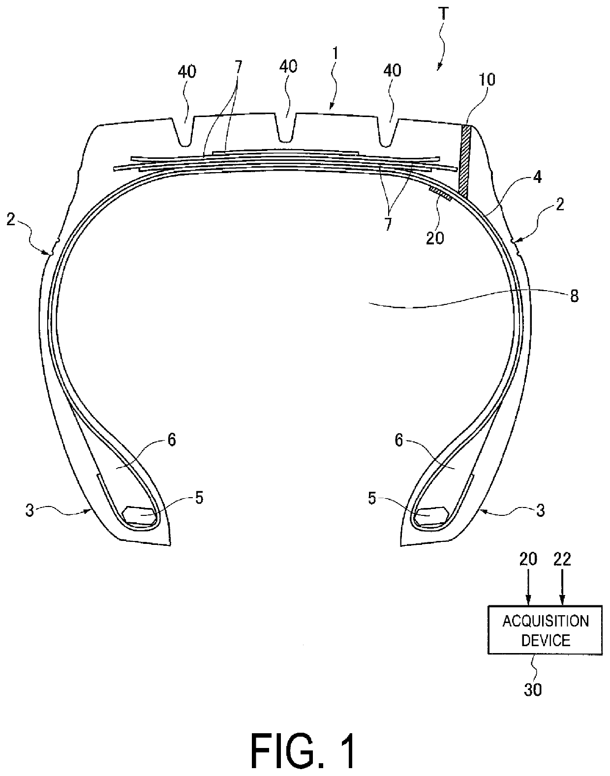
[0039]A pneumatic tire, a tire wear information acquisition system, and a pneumatic tire wear information acquisition method of an embodiment will be described in detail below.

[0040]In the present specification, “tire lateral direction” refers to the direction of the center axis of rotation of a pneumatic tire. “Tire circumferential direction” refers to a rotation direction in which a tread surface rotates, when the tire rotates about the center axis of rotation of the tire. “Tire radial direction” refers to the direction radiating from the center axis of rotation of the tire. “Outward in the tire radial direction” refers to the direction away from the tire rotation center axis. “Inward in the tire radial direction” refers to the direction towards the center axis of rotation of the tire.

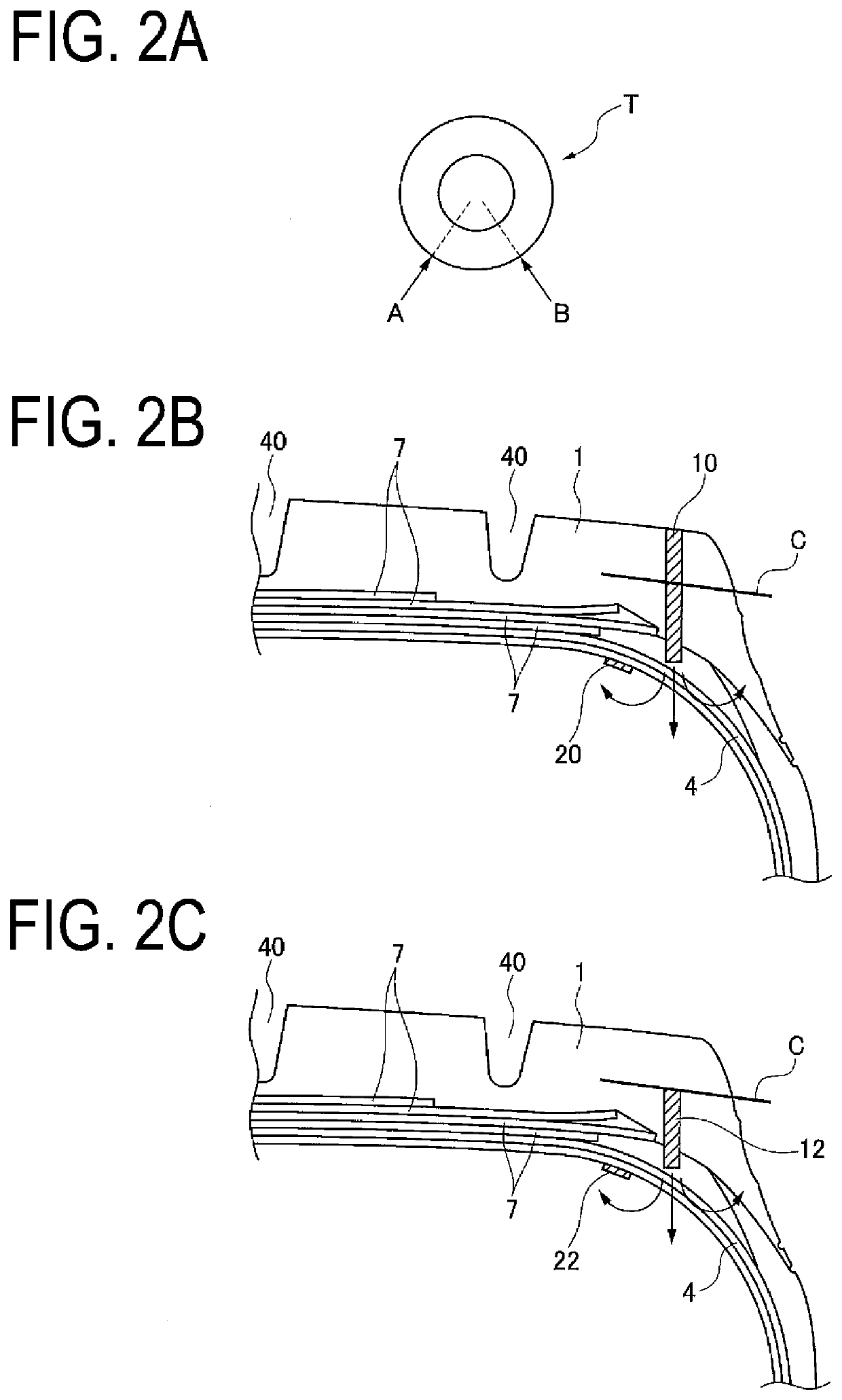
[0041]FIG. 1 is a profile cross-sectional view of a pneumatic tire (hereinafter, simply referred to as “tire”) T of an embodiment. As illustrated in FIG. 1, the pneumatic tire includes an annular tre...


PUM

PropertyMeasurementUnit
diameteraaaaaaaaaa
diameteraaaaaaaaaa
inclination angleaaaaaaaaaa

Abstract

A tread portion of a pneumatic tire includes a columnar wear measurement magnet that has magnetic flux density or magnetic field strength formed thereby decreased due to wear thereof along with wear of tread rubber of the tread portion and a columnar reference magnet provided at a position where the columnar reference magnet is not worn with the wear of the tread rubber. The wear measurement magnet and the reference magnet extend from a tread surface side toward a tire cavity region of the pneumatic tire, and an end of the reference magnet on the tread surface side is located farther from a tread surface where the tread portion contacts the ground than an end of the wear measurement magnet on the tread surface side.

Description

TECHNICAL FIELD[0001]The present technology relates to a pneumatic tire provided with a magnet for acquiring wear information regarding a tread portion, a tire wear information acquisition system that acquires wear information regarding a tread portion, and a pneumatic tire wear information acquisition method for a pneumatic tire provided with a magnet for acquiring wear information regarding a tread portion.BACKGROUND ART[0002]Conventionally, in managing the wear of the tread portion of a pneumatic tire, a driver or a vehicle supervisor visually inspects the wear state of the tire by observing and checking the groove depth in the tread pattern or the appearance of a slip sign provided in the pneumatic tire. When the tread rubber reaches the wear limit, the pneumatic tire is replaced with a new pneumatic tire. Visually observing and checking the wear state of the pneumatic tire is not preferable in a case where the driver or the like fails to inspect or the check method is incorrect...

Claims


Application Information

Patent Timeline
Patent Type & Authority Applications(United States)
IPC IPC(8): B60C11/24G01B7/26
CPCB60C11/246B60C2011/0341G01B7/26B60C11/243B60C2019/004G01B7/10B60C2019/005
Inventor TANNO, ATSUSHI
Owner THE YOKOHAMA RUBBER CO LTD
Why Eureka
Try Eureka