Permanent magnet synchronous motor

a permanent magnet, synchronous motor technology, applied in the direction of rotating magnets, synchronous machines with stationary armatures, magnetic circuit rotating parts, etc., can solve the problems of reducing efficiency, reducing the advantage of concentrated windings, and greatly increasing iron loss, so as to reduce the density of magnetic flux of stator cores, less magnetic salient poles, and high efficiency

Inactive Publication Date: 2005-08-30
PANASONIC CORP
View PDF23 Cites 9 Cited by
  • Summary
  • Abstract
  • Description
  • Claims
  • Application Information

AI Technical Summary

Benefits of technology

[0004]The present invention provides a rotor of a synchronous motor having both of permanent magnets and a stator using a concentrated winding method. On a section of the rotor laminated in a rotary shaft direction, arc-shaped or bow-shaped slits are provided. The projecting portion of the arc-shape or bow shape face to the outside rim of the rotor, and permanent magnets are inserted into the slits. This structure produces less magnetic salient poles than a conventional rotor, thereby reducing a magnetic flux density of the stator core. This structure can thus provide a highly efficient motor that incurs less loss.

Problems solved by technology

As a result, iron loss greatly increases although the copper loss decreases, so that efficiency is lowered, which render the advantage of the concentrated windings insignificant.

Method used


Image

  • Permanent magnet synchronous motor
  • Permanent magnet synchronous motor
  • Permanent magnet synchronous motor

Examples


exemplary embodiment 1

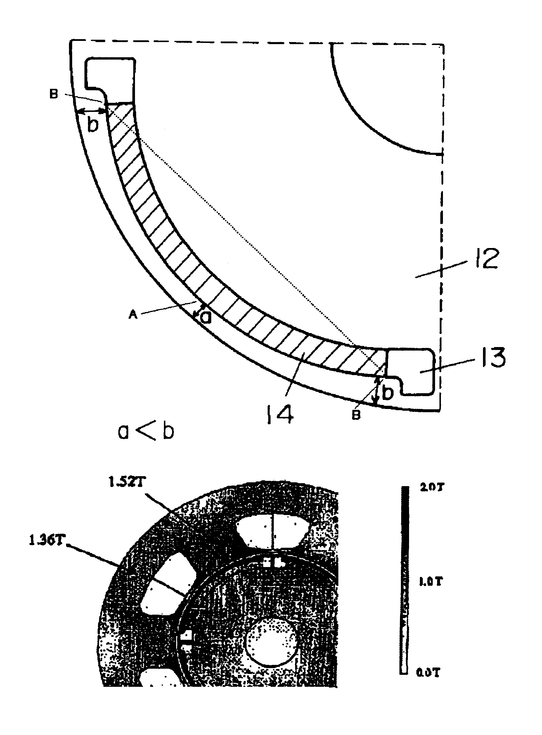
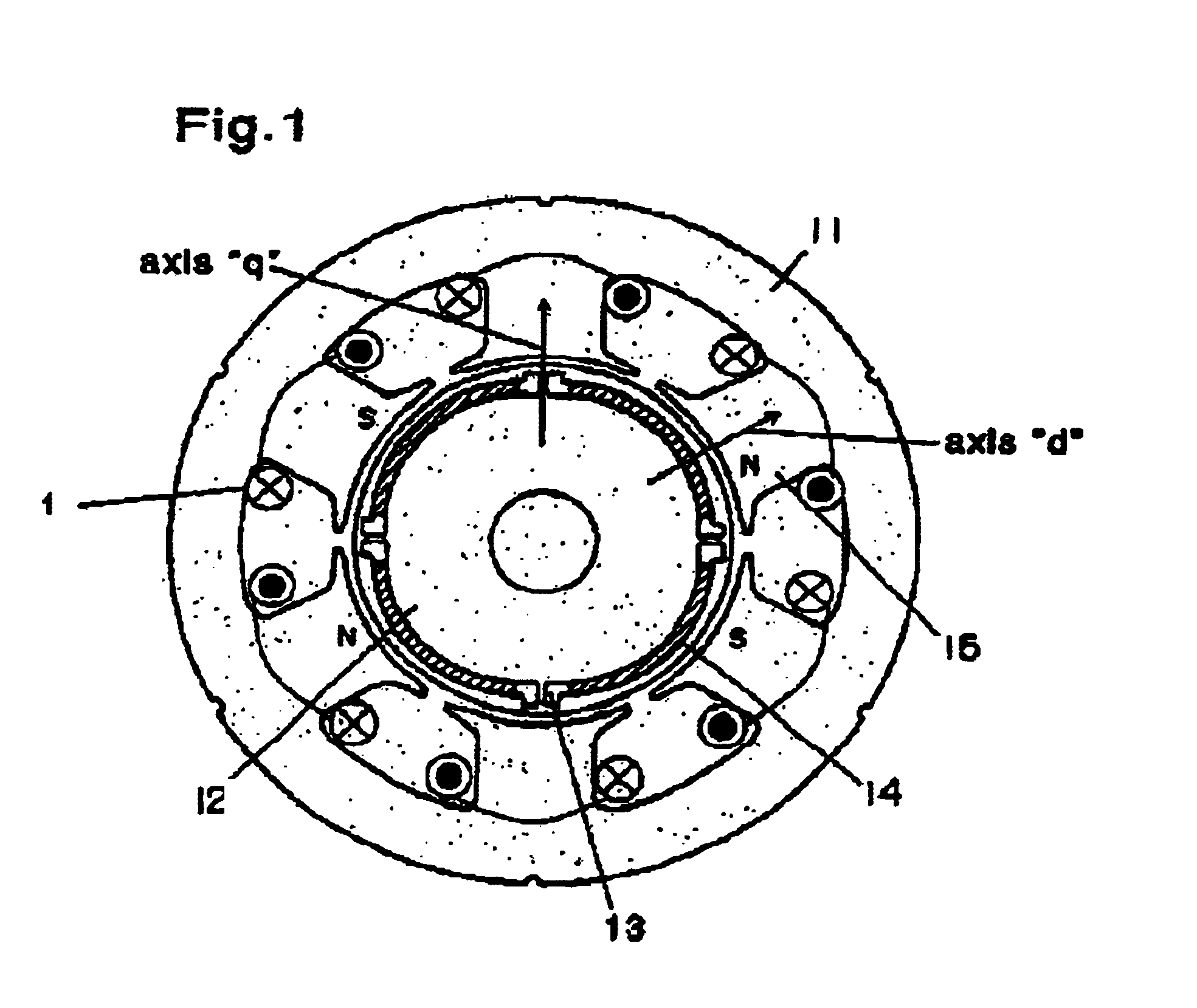
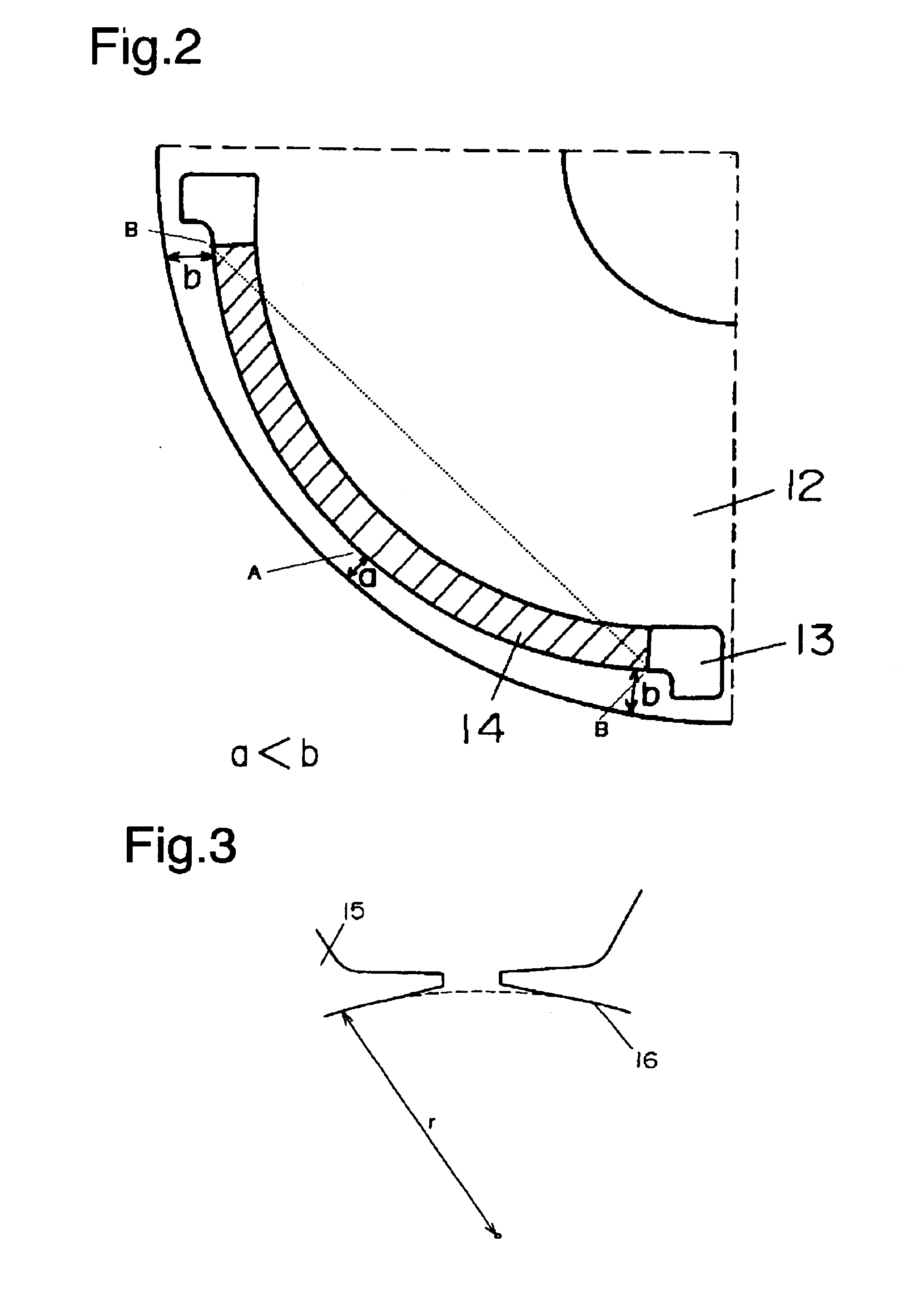
[0021]FIG. 1 illustrates the first exemplary embodiment, a structure is provided that includes a stator 11 employing concentrated windings 1, a rotor 12, slits 13, and permanent magnets 14 located in the slits. Stator 11 has three phases, four poles and six slots. Each one of teeth is wound independently with a winding, and two coils of each phase are apart 180 degrees from each other, i.e., opposite to each other. Stator 11 is formed by laminating plural electromagnetic steel sheets in a rotary shaft direction, and includes plural teeth. Ends of each one of teeth 15 slightly encroach into slots as shown in FIG. 3.

[0022]To be more specific, distance “r” between arc face 16, which faces to rotor 12, of stator 11 and the center of rotor 12 is smaller at a center portion of teeth 15 than at the end of teeth 15. (The broken line tangent to arc face 16 measures a constant distance “r” from the center of rotor 12.) This structure restrains demagnetizing field from flowing to rotor 12. Bec...

exemplary embodiment 2

[0029]FIG. 9 illustrates the second embodiment of the present invention. FIG. 9 illustrates a structure that includes a stator 21 that employs the concentrated windings 1, wherein V-shaped slits 23 are formed in a rotor 22, and wherein permanent magnets 24 are located in the slits 23. The vertex of each one of the V-shaped magnets faces toward the outside rim of the rotor. This structure also can narrow the flux path along axis “q” as discussed in the first embodiment, and thus can lower the iron loss. This structure produces a similar advantage to the first embodiment. Further, as shown in FIG. 9, the permanent magnet to be buried in each slit is divided in half, and two sheets of magnet shaped like a flat plate can be inserted into the slit. Thus an efficient motor of a lower cost, which uses inexpensive and flat magnets instead of expensive and arc-shaped magnets shown in FIG. 1, can be obtained.

[0030]The V-shaped magnet shown in FIG. 9 uses two sheets of permanent magnet in one ...

exemplary embodiment 3

[0031]FIG. 10 shows sectional view of a compressor which employs the synchronous motor having permanent magnets in accordance with the first exemplary embodiment. As shown in FIG. 10, the compressor comprises the stator 11 using the concentrated windings, rotor 12, the permanent magnets 14, an accumulator 31 and a compressing mechanism 32. The motor of this compressor has a shorter length including its coil end, and works efficiently, so that the compressor is best fit for a place where the power or the storage area is limited, such as an air-conditioner compressor C for an air-conditioning unit 104 for a vehicle 100, in particular an electric vehicle, for cooling a passenger compartment 102, as schematically illustrated in FIG. 10A.


PUM


Abstract

A structure of a rotor used in a synchronous motor employing both of permanent magnets and a stator using concentrated windings is disclosed. Slits (13) provided in a section of a rotor laminated in a direction of a rotary shaft are shaped like an arc or a bow, and the shape protrudes toward an outside rim of rotor (12). Permanent magnets (14) are inserted into slits (13). This structure produces less magnetic salient poles than a conventional rotor, so that a magnetic flux density can be lowered, and an efficient motor with less loss is obtainable.

Description

TECHNICAL FIELD[0001]The present invention relates to a synchronous motor equipped with both interior magnets and a stator using concentrated windings.BACKGROUND ART[0002]FIG. 11 shows a conventional synchronous motor equipped with interior magnets and a stator using concentrated windings. As shown in FIG. 11, the motor includes a stator 1 having concentrated windings, a rotor 2, slits 3 provided in the rotor, permanent magnets 4 located in the slits 3. Stator 1 is formed of a concentrated-winding stator having three phases, four poles and six slots. As shown in FIG. 12, respective teeth are wound with windings independently, and each phase includes two coils 180 degrees apart from each other, i.e., opposite to each other. Slits 3 shaped like a flat plate are prepared inside rotor 2, and permanent magnets having a similar shape to slit 3 are inserted in slits 3 respectively. As shown in FIG. 12, a motor using the concentrated windings provides independent windings to respective teet...

Claims


Application Information

Patent Timeline
Patent Type & Authority Patents(United States)
IPC IPC(8): H02K1/27
CPCH02K1/276
Inventor MURAKAMI, HIROSHINISHIYAMA, NORIYOSHIKISHIBE, TAROKADO, HARUHIKOTAMAMURA, TOSHIYUKIKATAOKA, HISAKAZUSHINTO, MASAYUKIMORINO, OSAAKI
Owner PANASONIC CORP
Why Eureka
Try Eureka