Method for manufacturing laminated iron core and apparatus for manufacturing laminated iron core

a technology of laminated iron and manufacturing method, which is applied in the manufacture of magnetic cores, transformers/inductance details, electrical devices, etc., can solve the problems of difficult high-accuracy blanking, achieve convenient position adjustment of die units, and shorten time-consuming for position adjustmen

Active Publication Date: 2017-09-28
MITSUI HIGH TEC INC +1
View PDF11 Cites 0 Cited by
  • Summary
  • Abstract
  • Description
  • Claims
  • Application Information

AI Technical Summary

Benefits of technology

[0032]The method and the apparatus for manufacturing the laminated iron core according to the aspects of the present invention simultaneously blank the front end side of the magnetic pole piece part and the back surface side of the yoke piece part of each of the iron core pieces in the case of blanking the pair of iron core pieces from the strip-shaped workpiece, with the result that accuracy of a dimension ranging from a front end of the magnetic pole piece part to a back surface of the yoke piece part can be improved. Also, in the case of blanking the iron core pieces, a position adjustment of the die unit can be made with respect to each of the iron core pieces, with the result that the position adjustment of the die unit is facilitated, and time consuming for the position adjustment can also be shortened.
[0033]Consequently, the iron core piece can be blanked from the strip-shaped workpiece with good workability and high accuracy.
[0034]Also, when the back surface side of the yoke piece part of each of the iron core pieces is blanked at the distance in the longitudinal direction of the yoke piece part, a press load in this blanking step can be decreased.
[0035]And, in the case of blanking the portion between the opposed lateral parts of the mated magnetic pole piece parts, this blanking causes expansion in the strip-shaped workpiece. As a result, by simultaneously blanking the front end side of the magnetic pole piece part and the back surface side of the yoke piece part of each of the iron core pieces after this blanking, the accuracy of the dimension ranging from the front end of the magnetic pole piece part to the back surface of the yoke piece part can be improved, with the result that, for example, the number of position adjustments of the die unit can be decreased.

Problems solved by technology

This problem can be partly solved by adjusting a position of the die unit, but the dimensions S cannot be adjusted individually, with the result that even when the dimension of one row has no problem, it becomes necessary to adjust the dimension of the other row and consequently it becomes difficult to perform high-accuracy blanking.

Method used


Image

  • Method for manufacturing laminated iron core and apparatus for manufacturing laminated iron core
  • Method for manufacturing laminated iron core and apparatus for manufacturing laminated iron core
  • Method for manufacturing laminated iron core and apparatus for manufacturing laminated iron core

Examples


Embodiment Construction

[0042]Subsequently an embodiment of the present invention will be described with reference to the accompanying drawings, and the present invention will be understood.

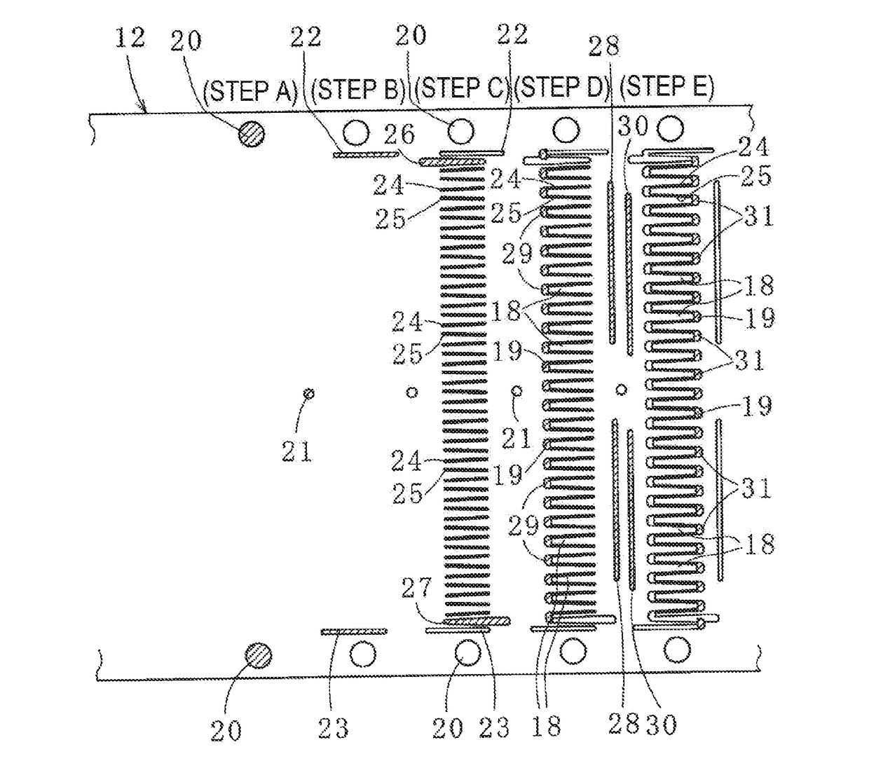
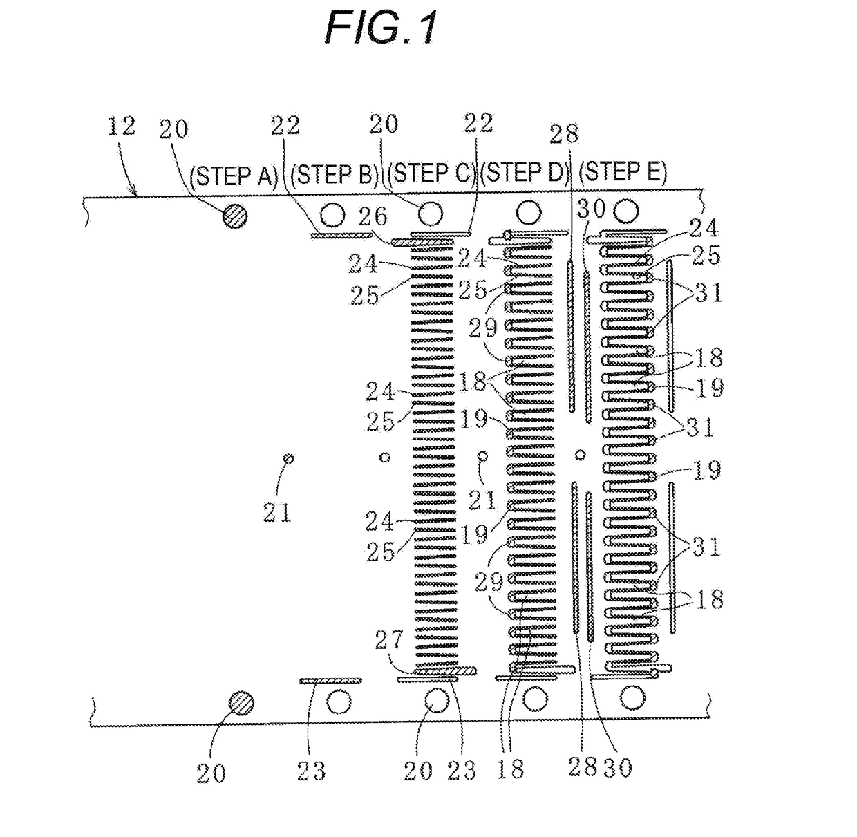
[0043]First, a laminated iron core manufactured by a method for manufacturing the laminated iron core according to one embodiment of the present invention be described with reference to FIGS. 1 and 2,

[0044]The laminated iron core is a stator iron core (or simply referred to as stator) used in an inner rotor type.

[0045]This laminated iron core is formed by laminating a plurality of sets of a pair of (paired) iron core pieces 10, 11.

[0046]Each of the iron core pieces 10, 11 is blanked and formed from a strip-shaped workpiece (thin metal sheet) 12 made of, for example, an amorphous material or an electromagnetic steel plate with a thickness of about 0.10 to 1.2 mm. In FIGS. 1 and 2, the width (the length of each of the iron core pieces 10, 11 in a longitudinal direction) of the strip-shaped workpiece 12 is narrowed and des...


PUM

PropertyMeasurementUnit
thicknessaaaaaaaaaa
distanceaaaaaaaaaa
magneticaaaaaaaaaa

Abstract

A method for manufacturing a laminated iron core includes setting a blanking position on a strip-shaped workpiece for iron core pieces each including a yoke piece part having a linear shape and a magnetic pole piece part extending from the yoke piece part, such that a pair of iron core pieces are opposed each other and the magnetic pole piece part of one iron core piece is arranged between adjacent magnetic pole piece parts of the other iron core piece among the pair of iron core pieces, simultaneously blanking a front end side of the magnetic pole piece part and a back surface side of the yoke piece part of the one iron core piece from the strip-shaped workpiece before simultaneously blanking those of the other iron core piece from the strip-shaped workpiece, and blanking the iron core pieces from the strip-shaped workpiece.

Description

CROSS REFERENCE TO :RELATED APPLICATION[0001]This application is based upon and claims the benefit of priority of Japanese Patent Application No. 2016-057136 filed on Mar. 22, 2016, the contents of which are incorporated herein by reference in its entirety.BACKGROUND OF THE INVENTION[0002]1. Field of the Invention[0003]The present invention relates to a method for manufacturing a laminated iron core formed by blanking iron core pieces from a strip-shaped workpiece and laminating the iron core pieces, and an apparatus for manufacturing the laminated iron core.[0004]2. Description of the Related Art[0005]A method for manufacturing a laminated iron core includes, for example, the following methods (A) to (C).[0006]Method (A): The method for laminating linear strip-shaped iron core pieces (by one wind) blanked and formed from a strip-shaped workpiece by a die unit and forming a strip-shaped laminated iron core and annularly folding this strip-shaped laminated iron core and forming a lam...

Claims


Application Information

Patent Timeline
Patent Type & Authority Applications(United States)
IPC IPC(8): H01F41/02
CPCH01F41/0213H02K15/02H01F3/02H01F3/04H01F27/245H01F27/25H01F27/26H01F41/0206H01F41/0233H01F2003/005
Inventor HASHIMOTO, AKIHIROFURUTA, MASAHIKOGOTO, TOSHIOHARADA, YOSHIHIROIMAZAWA, YOSHIRO
Owner MITSUI HIGH TEC INC
Why Eureka
Try Eureka