Photovoltaic mounting system with sealant injector inlet

a technology of photovoltaic energy and mounting system, which is applied in the direction of photovoltaic supports, heat collector mounting/support, lighting and heating apparatus, etc., can solve the problems of causing another potential leakage point, affecting installation efficiency, and relatively high price of flashings, etc., and achieves the effect of increasing load

Active Publication Date: 2017-09-28
TESLA INC
View PDF3 Cites 18 Cited by
  • Summary
  • Abstract
  • Description
  • Claims
  • Application Information

AI Technical Summary

Benefits of technology

[0018]In any of the embodiments described herein, the mounting plate can be sized and dimensioned to extend near a bottom perimeter of the mounting shell, for example, within about 5 inches or less of the bottom perimeter. In some embodiments, the mounting plate extends just outside of the bottom perimeter to distribute loading forces applied through the metal puck or shell. In other embodiments, the mounting plate is about flush with the outer perimeter of the mounting shell. In still other embodiments, the mounting plate extends just inside of the bottom perimeter such that a load is applied predominately through a sidewall of the metal puck or shell. In some embodiments, the mounting plate includes an extended portion, a reinforced portion and/or a raised portion along a bottom down-roof side so as to withstand the increased load in the down-roof portion of the mounting puck or shell a...

Problems solved by technology

Although flashings cover up a lot of space, potentially covering mis-drilled or off-center pilot holes, flashings are relatively expensive because they require more metal than direct mounted solutions.
Each time a nail is removed, another potential leak point is created.
This can be messy for the installer, requires a separate large and bulky tool (e.g., caulk gun), and requires another pro...

Method used


Image

  • Photovoltaic mounting system with sealant injector inlet
  • Photovoltaic mounting system with sealant injector inlet
  • Photovoltaic mounting system with sealant injector inlet

Examples


Embodiment Construction

[0037]The following description is intended to convey a thorough understanding of the embodiments described by providing a number of specific embodiments and details involving PV mounting hardware for shingled roofs. It should be appreciated, however, that the present invention is not limited to these specific embodiments and details, which are exemplary only. It is further understood that one possessing ordinary skill in the art, in light of known systems and methods, would appreciate the use of the invention for its intended purposes and benefits in any number of alternative embodiments, depending upon specific design and other needs.

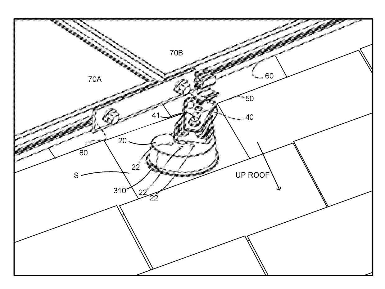
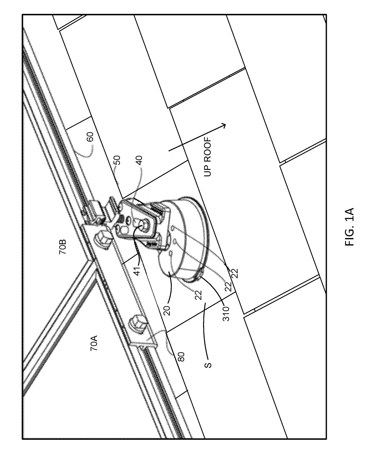
[0038]Referring now to FIG. 1A, mounting system 100 includes a mounting plate 310 that conforms closely to the size and shape of mounting puck 20 to allow mounting of a conventional off-the-shelf mounting puck without modifying shingles S of the roof surface and / or without using traditional metal flashing. Leveling support arm 40 is secured to one of ...


PUM


Abstract

Photovoltaic mounting systems that form chemical flashings are provided herein. Such mounting systems can include a mounting plate adapted to interface with an off-the-shelf mounting puck so as to allow mounting of the puck on the roof surface without use of traditional roof flashing and/or modification of shingles of the roof surface. Such mounting plates can include a top surface adapted to interface with the puck and a bottom surface that defines a cavity between the mounting plate and the puck in which to form the chemical flashing by injecting a flowable sealant into the cavity via an inlet of the mounting plate that remains accessible from outside the puck during mounting. Such mounting plates can further include features for orienting the plate, directing runoff away from any sealed roof penetrations and filling of the cavity with flowable sealant.

Description

CROSS-REFERENCE TO RELATED APPLICATIONS[0001]This is related to U.S. Provisional Patent Application No. 62 / 260,178 [Atty Docket No. P124-3PUS] filed on Nov. 25, 2015 and U.S. Provisional Patent Application No. 62 / 120,841 [Atty Docket No. P124-1PUS] filed on Feb. 25, 2015; Non-Provisional patent application No. 14 / 949,820 [Atty Docket No. P124-2NUS] filed on Nov. 23, 2015 and Non-Provisional patent application Ser. No. 15 / 007,154 [Atty Docket No. P235-1NUS] filed on Jan. 26, 2016; each of which is incorporated herein by reference in its entirety for all purposes.FIELD OF THE INVENTION[0002]The invention relates to photovoltaic energy generation mounting systems and more specifically to systems, devices and methods for installing photovoltaic (PV) modules on composition shingle roofs.BACKGROUND[0003]Although total market penetration of solar into the relevant base of potential customers remains relatively low in the United States (e.g. less than about one percent), residential and com...

Claims


Application Information

Patent Timeline
IPC IPC(8): H02S20/23E04D13/15E04D13/00
CPCH02S20/23E04D13/15E04D13/00F24S25/61F24S2025/021Y02B10/10Y02B10/20Y02E10/47Y02E10/50F24S25/60
Inventor SEERY, MARTINBAUTISTA, GARRET
Owner TESLA INC
Why Eureka
Try Eureka