
Wildlife feeder varmint shield

a feeder and varmint shield technology, applied in the field of wildlife feeders, can solve the problems of increased cost for wildlife enthusiasts and costly repairs, and achieve the effect of reducing structural rigidity

Active Publication Date: 2017-10-05
YOUNG TIMOTHY JOE
View PDF2 Cites 9 Cited by
  • Summary
  • Abstract
  • Description
  • Claims
  • Application Information

AI Technical Summary

Benefits of technology

The present disclosure is a varmint shield for a wildlife feeder that prevents unauthorized animals from accessing and eating the feeder's food. The shield is designed to be attached to the feeder's legs using screws or other fastening means. The shield is made of a flexible material that deflects feed expelled from the feeder outward, away from the feeder. The shield also has edges and cuffs for structural strength and includes a first and second shoulder to aid in installation. Additionally, the shield produces an audible noise when the feeder motor goes off, which alerts desirable animals to the feeder's activity. The crease and mounting holes allow for easy installation and can be used to secure a shield to each leg of the feeder for additional protection. Overall, the varmint shield saves money by preventing feed waste and attracts desirable animals to the feeder, improving its usefulness.

Problems solved by technology

Wildlife feeders are commonly placed in remote locations and left unattended for substantial periods of time.
One known and persistent problem with wildlife feeder operation is the fact that varmints are known to climb the legs of the wildlife feeder in an effort to access the feed within the hopper.
This results in a greater expense to the wildlife enthusiast who must consistently refill the hopper.
Another known problem is that varmints which do access the feeder hopper are known to break solar panels and cut electrical wiring resulting in costly repairs.

Method used


Image

  • Wildlife feeder varmint shield
  • Wildlife feeder varmint shield
  • Wildlife feeder varmint shield

Examples


Embodiment Construction

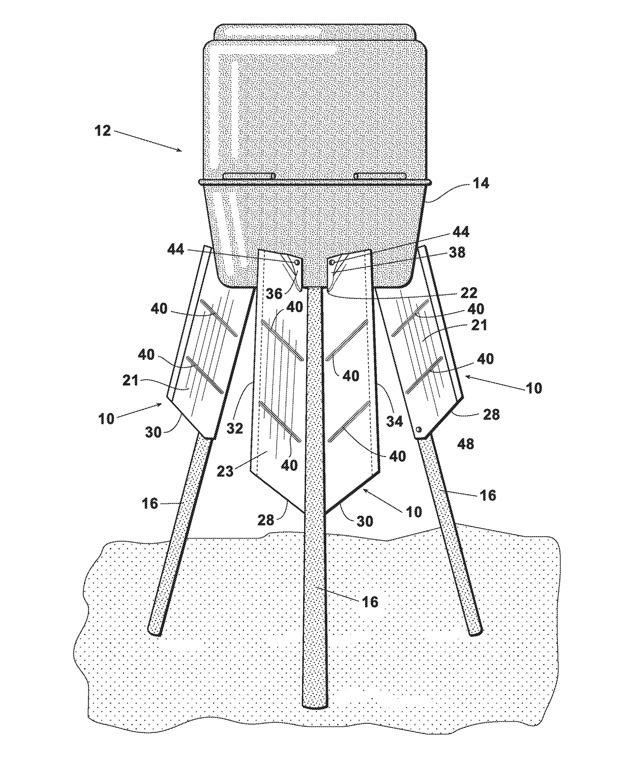
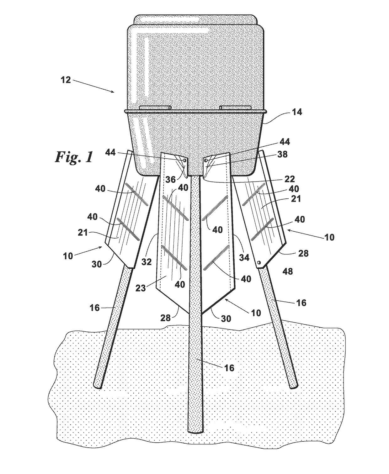
[0024]With reference to the FIGS., FIG. 1 depicts an exemplary wildlife feeder 12 including a plurality of varmint shields, collectively 10 affixed thereon. It should be understood that the wildlife feeder depicted is exemplary and commercially available in various configurations. As such, the wildlife feeder itself, unless configured with the varmint shield of the present disclosure, does not form a part of the present invention. Wildlife feeder 12 includes a typically configured storage hopper 14 and a plurality of legs 16 supporting storage hopper 14. Storage hopper 14 includes an amount of bulk feed stored therein to be dispensed by feeder 12 over time. Wildlife feeder 12 further includes a motor 18 (see FIG. 6), and typically positioned below hopper 14, in feed (typically by gravity) communication which distributes feed from hopper 14 on an interval, commonly timed, basis. As such, wildlife feeders commonly include a timer in electrical communication with the motor as well as a...


PUM


Abstract

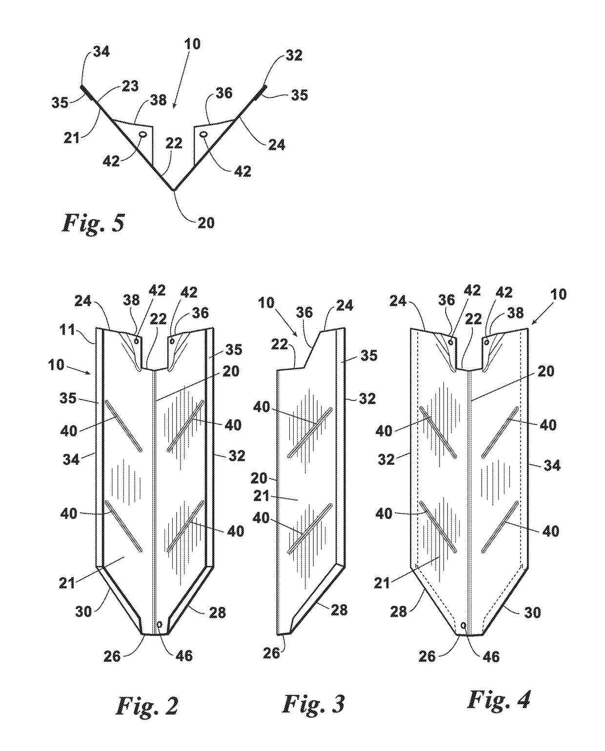
The present disclosure includes a varmint shield for a wildlife feeder supported by at least one leg. The varmint shield includes a body having a length, a back side and a front side, a top end and a bottom end; and a first side and a second side. A notch is cut in the top end of the body. A plurality of mounting tabs are formed by bending the body at the notch toward the front side, each including at least one hole for receiving a fastening means such as a screw for securing the body to the wildlife feeder. The body of the varmint shield is bent along its length from the top end to the bottom end at an angle sufficient to deflect feed expelled from the wildlife feeder outwardly and away from the wildlife feeder. The body may also include beads formed along its length for structural strength and cuffs folded along its edges. A first shoulder and a second shoulder are preferably cut in the bottom end of the body. The first shoulder and the second shoulder preferably include edges folded to form cuffs. These cuffs aid in structural rigidity. At least one hole may be drilled in the body adjacent the bottom end for securing the body to the at least one leg of the wildlife feeder.

Description

CROSS REFERENCE TO RELATED APPLICATION[0001]This application claims the benefit of U.S. Provisional Application No. 62 / 390,613 filed Apr. 4, 2016, herein incorporated by reference in its entirety for all purposes.FIELD OF THE INVENTION[0002]The present invention relates to wildlife feeders and particularly devices for the prevention of varmints from accessing the food contained / stored within the wildlife feeder.BACKGROUND OF THE INVENTION[0003]Wildlife feeders are commonly used by hunters and other wildlife enthusiasts in order to attract wildlife such as deer, turkey, and other such animals. Wildlife feeders are commonly placed in remote locations and left unattended for substantial periods of time. A volume of feed, such as typically corn, are held by the wildlife feeder and distributed at set intervals. Wildlife then frequent the feeder locations and consume the feed. Wildlife cameras are typically positioned near wildlife feeders to record, either still or video, the animals whi...

Claims


Application Information

Patent Timeline
IPC IPC(8): A01K5/02
CPCA01K5/0225A01M31/008A01K5/0291
Inventor YOUNG, TIMOTHY JOE
Owner YOUNG TIMOTHY JOE
Learn More