
Packaging of solid state devices

a solid-state device and packaging technology, applied in the direction of semiconductor devices, semiconductor/solid-state device details, electrical apparatus, etc., can solve the problems of increasing time and material costs, increasing complexity, and increasing the difficulty of assembly of packages, so as to achieve high current conduction, high operating voltage, and high current conduction

Active Publication Date: 2005-08-25
EXCELITAS TECH
View PDF11 Cites 0 Cited by
  • Summary
  • Abstract
  • Description
  • Claims
  • Application Information

AI Technical Summary

Benefits of technology

[0010] The invention is a method of packaging solid state devices capable of high current conduction, high operating voltage, or both high current conduction and high operating voltage. The method of packaging allows for electrical insulation for high voltages, dissipation of large quantities of heat, structural rigidity, long life-time reliability, low cost for manufacturing, and compactness. This method of packaging will allow for more economical assembly of complicated solid state systems. The packaging enables low inductance internal and external connections to enable operation at high rates of current rise versus time.

Problems solved by technology

As the number of interconnections increases, the assembly of the package becomes more difficult.
Examples of the increases in complexity include connecting to the gate of a thyristor, or with multiple devices, the interconnection of devices in parallel or in series.
However, such methods increase the cost in time and material.
The package has to insulate above the maximum operating voltage to prevent breakdown and shorting, resulting in damage to the package.
Power loss reduces efficiency while heating can cause localized stress.
These large induced voltages occur during rapid changes in current conduction versus time and can cause solid state devices to improperly change state, from conducting to non-conducting or from non-conducting to conducting.
High interconnection inductance increases the trigger system requirements and limits applications for the devices.
Another important issue for packaging solid state devices is to prevent the exposure of the solid state devices to an oxidizing environment, both during the packaging and in use.

Method used

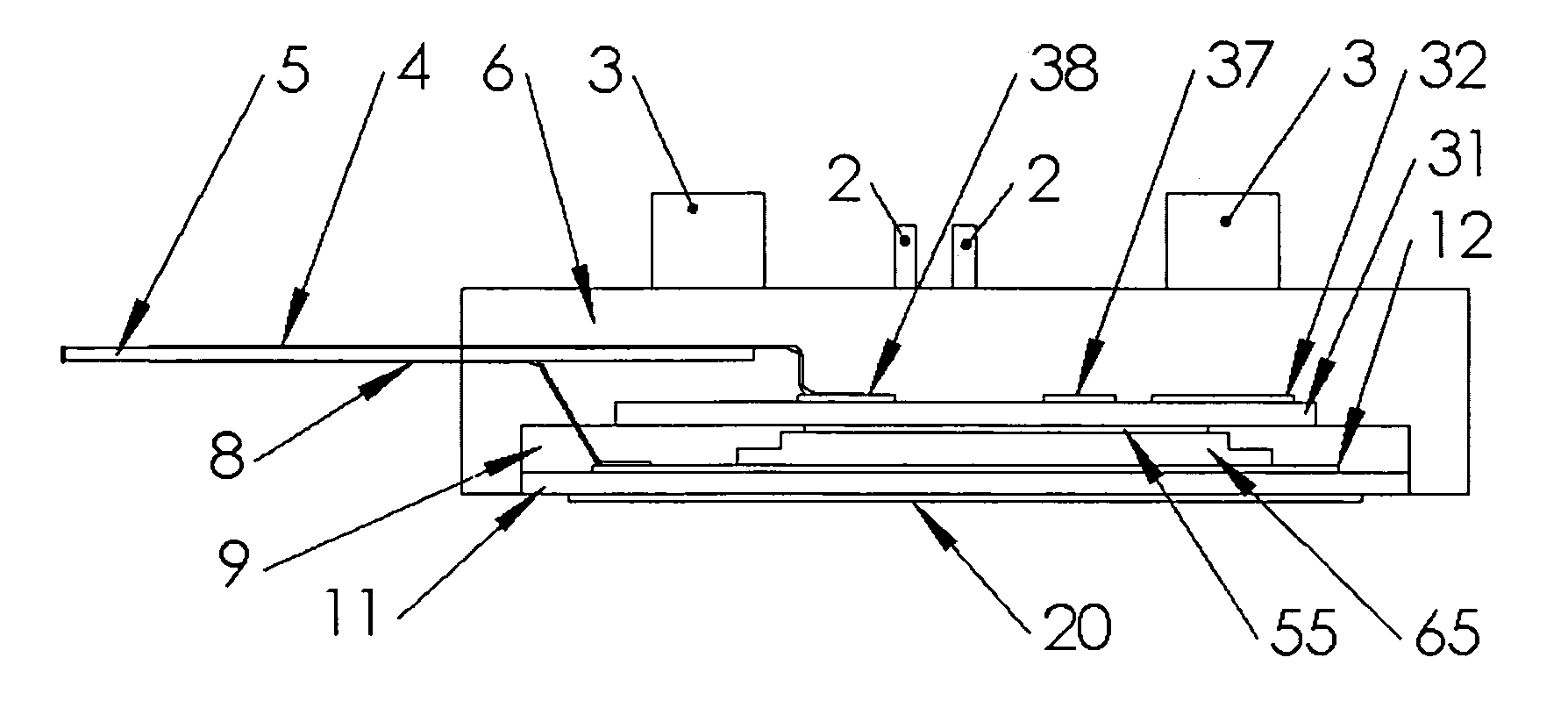

Image

  • Packaging of solid state devices
  • Packaging of solid state devices
  • Packaging of solid state devices

Examples


Embodiment Construction

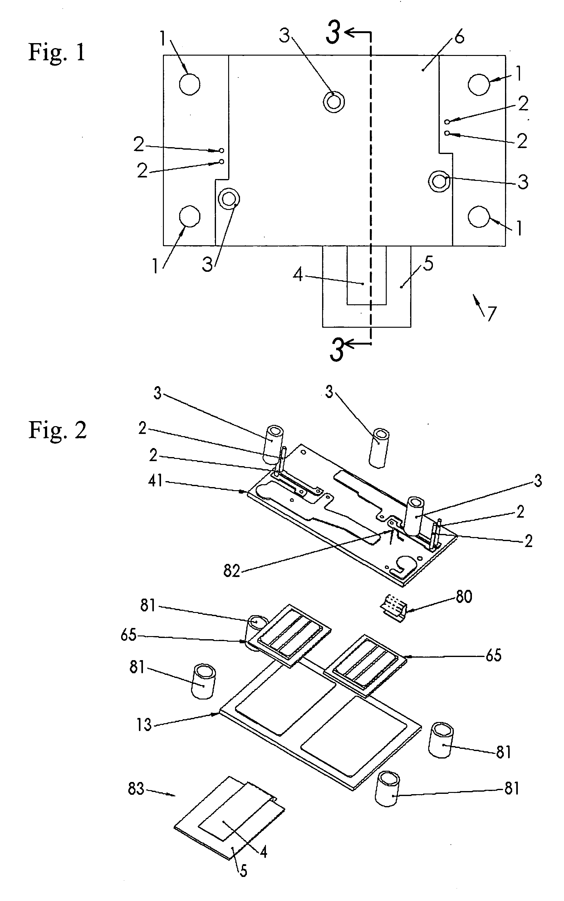
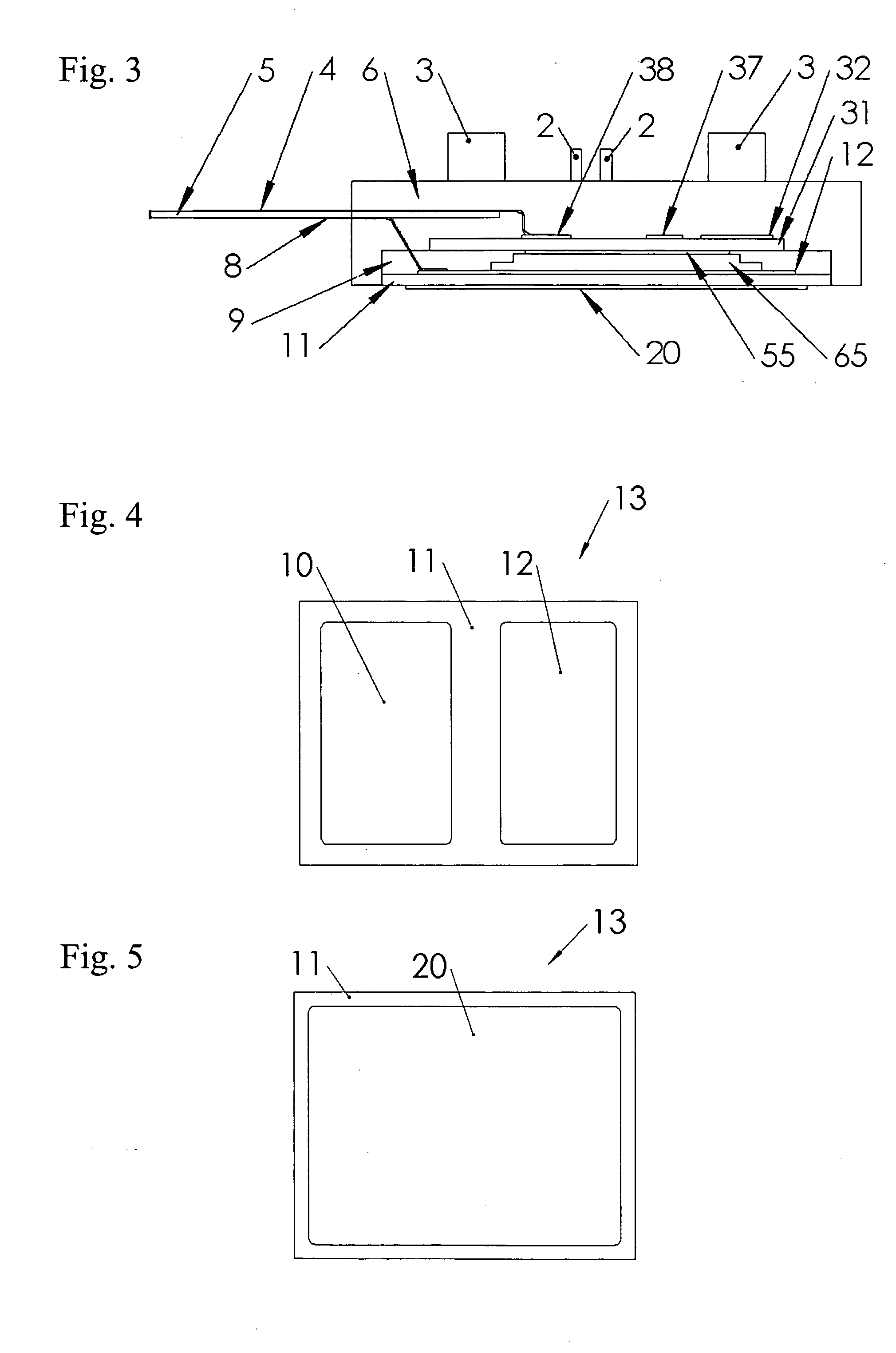
[0024] One example of the method of packaging of solid state devices of this invention is depicted in FIG. 2. It comprises one or more solid state devices 65, two layers of metallized ceramic substrate 13, 41, two encapsulants 6, 9, metal threaded 3 and pin terminals 2, and metal strip-lines 83. Ceramic substrates 13, 41 are used because of ceramic's excellent electrical insulating properties, high thermal conductivity and low thermal coefficient of expansion. The encapsulants 6, 9 provide further electrical insulation over the rest of the package while also preventing exposure of the components to oxidizing agents and providing structural rigidity and durability. Metal threaded 3 and pin terminals 2 are used to provide low power electrical connections to external circuits.

[0025] The strip-line 83 can also be seen in the sectional view of FIG. 3. The strip-line consists of conductive strips 4, 8 separated by an insulator 5 with a high dielectric strength, such as Kapton, and are us...


PUM


Abstract

A package for one or more solid state devices in a single module that allows for operation at high voltage, high current, or both high voltage and high current. Low thermal resistance between the solid state devices and an exterior of the package and matched coefficient of thermal expansion between the solid state devices and the materials used in packaging enables high power operation. The solid state devices are soldered between two layers of ceramic with metal traces that interconnect the devices and external contacts. This approach provides a simple method for assembling and encapsulating high power solid state devices.

Description

ACKNOWLEDGMENT OF GOVERNMENT SUPPORT [0001] This invention was made with Government support under Grant No. DE-FG02-00ER82948, awarded by the Department of Energy. The government has certain rights in the invention.BACKGROUND OF THE INVENTION [0002] 1. Field of the Invention [0003] The invention pertains to the field of packaging solid state devices. More particularly, the invention pertains to packaging high power solid state devices used to control high voltage, high current, or both high voltage and high current, in areas such as pulsed power for electromagnets, lasers, ion sources, X-ray sources, and other applications. [0004] 2. Description of Related Art [0005] Packaging of high power solid state devices, such as diodes, transistors, and thyristors, has to encompass the interconnection of the devices and external contacts, heat dissipation for up to hundreds of watts of heat, and electrical insulation for up to thousands of volts. Typically, these packages include a base, such...

Claims


Application Information

Patent Timeline
Patent Type & Authority Applications(United States)
IPC IPC(8): H01L23/12H01L23/31H01L23/538H01L25/07
CPCH01L23/3135H01L23/5385H01L25/072H01L2924/13055H01L2924/13091H01L2924/0002H01L2924/3011H01L2924/00
Inventor GLIDDEN, STEVEN C.SANDERS, HOWARD D.
Owner EXCELITAS TECH
Learn More