Illuminated Rotating Dance Pole

a technology of dancing poles and rotating poles, which is applied in the direction of gymnastic exercise, sport apparatus, transportation and packaging, etc., can solve the problems of inability to easily smooth and non-splinter materials, large diameters are generally less suitable for users' hands, and many non-metallic materials are poorly suited for use in dancing poles

Active Publication Date: 2017-10-05
FLICKER POLE L L C
View PDF7 Cites 9 Cited by
  • Summary
  • Abstract
  • Description
  • Claims
  • Application Information

AI Technical Summary

Benefits of technology

[0006]A dance pole effective to bear the weight of a dancer has a rigid inner core and a transparent outer tube circumscribing the rigid inner core. A first portion of an outer surface of the rigid inner core contacts an inner wall of the transparent outer tube and a second portion of the outer surface is recessed from the inner wall. A plurality of lighting points, such as strips of light emitting diodes, is disposed on the second portion of the outer surface.

Problems solved by technology

Larger diameters are generally usually less suitable to accommodate a user's hands.
For this reason, many non-metallic materials are poorly suited for use in dance poles, as are materials that cannot be easily made smooth and non-splintering.
A disadvantage of metal poles is that they are opaque.
Certain composite materials, such as fiberglass and carbon fiber, have sufficient strength and flex properties for use as dance poles, however, these composites, as with metals, are opaque.
However, these poles are not sufficiently rigid and suffer from undesired deflection during use when of the necessary height.
Hollow tubes containing illumination would suffer from even worse and unsatisfactory deflection.

Method used


Image

  • Illuminated Rotating Dance Pole
  • Illuminated Rotating Dance Pole
  • Illuminated Rotating Dance Pole

Examples


first embodiment

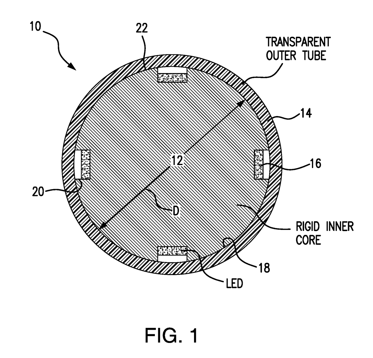
[0015]Disclosed is an internally illuminated dance pole that is sufficiently rigid for acrobatics. In a first embodiment, as illustrated in FIG. 1, the dance pole 10 has a rigid inner core 12 that is circumscribed by a transparent outer tube 14. The inner core provides substantially all of the dance pole 10 rigidity and houses illumination devices 16. One exemplary illumination device 16 is light emitting diodes (LEDs). As discussed below, the transparent outer tube 14, a base and a top may be configured to rotate on bushings and / or bearings as a unit. Bushings may optionally support the transparent outer tube 14 while also enabling several LED strips to pass through them.

[0016]Without limitation, materials suited for the transparent outer tube 14 include polycarbonate, acrylic, butyrate and polyvinyl chloride. Other plastics may be suitable as well. The rigid inner core 14 is preferably a metal or metal alloy, but may also be fiberglass, carbon fiber or other material that provides...

second embodiment

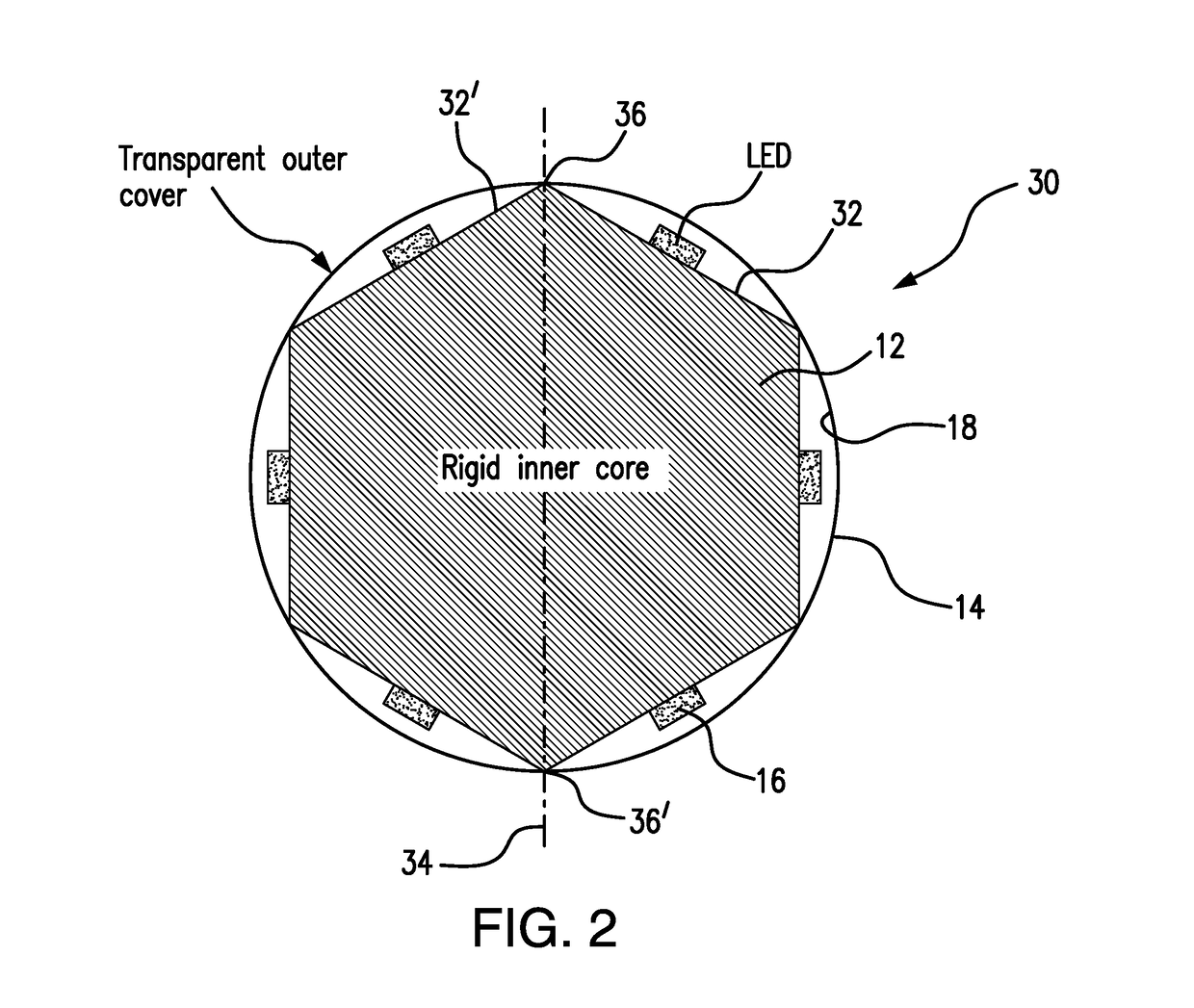
[0019]In a second embodiment, as illustrated in FIG. 2, a dance pole 30 has a rigid inner core 12 with a polygonal cross section. The number of flats 32 preferably matches the number of LED 16 strips desired. An axis 34 connecting two apexes 36, 36′ formed by an intersection of two adjoining flats 32, 32′ where the two apexes 36, 36′ are separated by 180°, has a length effective to support the transparent outer tube 14 without engaging the inner wall 18 such that one of the rigid inner core 12 and transparent outer tube 14 may rotate independent of the other. Alternatively, the transparent outer tube 14 may engage the inner wall 18 such that the rigid inner core 12 and transparent outer tube 14 rotate together. The exact dimensions of the rigid inner core 12 are dependent on the specific illumination devices, power connections and control devices.

[0020]With reference to FIG. 3, embodiments may employ either or both of a rotating rigid inner core 12 and rotating transparent outer tub...


PUM


Abstract

A dance pole effective to bear the weight of a dancer has a rigid inner core and a transparent outer tube circumscribing the rigid inner core. A first portion of an outer surface of the rigid inner core contacts an inner wall of the transparent outer tube and a second portion of the outer surface is recessed from the inner wall. A plurality of lighting points, such as strips of light emitting diodes, is disposed on the second portion of the outer surface.

Description

CROSS-REFERENCE TO RELATED PATENT APPLICATION[0001]This patent application claims a benefit to U.S. Provisional Patent Application Ser. No. 62 / 317,904, titled “Illuminated Rotating Dance Pole,” by James Glasner et al., that was filed on Apr. 4, 2016. The disclosure of U.S. 62 / 317,904 is incorporated by reference herein in its entirety.BACKGROUND OF THE DISCLOSURE[0002]A typical dance pole is a hollow brass pole approximately 8 feet in length that extends from a floor to a ceiling. Metal tubes having a diameter of around 2 inches are generally well suited for the typical uses of dancers. The diameter is sufficient to provide adequate stiffness, friction, and appearance at a reasonable cost. Larger diameters are generally usually less suitable to accommodate a user's hands. Both fixed and rotating metal dance poles are widely used. Polished brass and stainless steel are widely used for dance poles. An assortment of coatings may be applied over these metals to accommodate the decor of ...

Claims


Application Information

Patent Timeline
Patent Type & Authority Applications(United States)
IPC IPC(8): A63B71/06H02J7/02A63B9/00
CPCA63B71/0622A63B2244/225H02J7/025A63B9/00A63B2225/50A63B2225/74
Inventor GLASNER, JAMESNELSON, MARK
Owner FLICKER POLE L L C
Why Eureka
Try Eureka