Lanyard System

a technology of lanyards and straps, which is applied in the field of tools, can solve the problems of no reference to tethering the pieces to the tool, no reference to the tool, and no reference to the piece suitable for use, so as to prevent or reduce the interfering of the straps and achieve sufficient tensional force

Active Publication Date: 2017-10-05
BRULL JAMES GREGORY
View PDF70 Cites 6 Cited by
  • Summary
  • Abstract
  • Description
  • Claims
  • Application Information

AI Technical Summary

Benefits of technology

[0010]The present invention is a novel lanyard system for a piece that is securely connected to and released from a tool by a piece receiver that includes a lanyard assembly with a two ended strap and a retraction system fixed to the tool in a storage region of the tool. In particular, the first end of the strap is connected to the piece and the second end of the strap is connected to one end of the retraction system. The other end of the retraction system is connected to the tool. The strap is of sufficient length for the retraction system to retract a piece to the storage region after disconnection from the piece receiver. It is contemplated that the retraction system includes at least one spring (coil or helical) to cause the lanyard system to remain under tension while the piece is mounted in a piece receiver, thereby preventing or at least reducing the strap from interfering with the task at hand, the piece, the piece receiver or tool itself. The retraction system has sufficient tensional force to cause the retraction of a piece to the storage region once released from the piece receiver or work region of the tool.

Problems solved by technology

However, the challenge arises in keeping track of the multiple pieces to be placed in the piece receiver (chuck or quick change coupler).
Yet none of the references discussed above provide for a means to tether the pieces to the tool.
While such tethers are suitable for tethering a chuck key, none are suitable for use with a piece, like a screw bit, that is mounted in the piece connector.
The problem being that the tethers disclosed are of fixed length and must be manually guided or positioned to remain clear of the tool's work area around the piece connector.
In certain situations, such a tether could become entangled with the piece, piece connector or the tool itself resulting in unsafe conditions.

Method used


Image

  • Lanyard System
  • Lanyard System
  • Lanyard System

Examples


Embodiment Construction

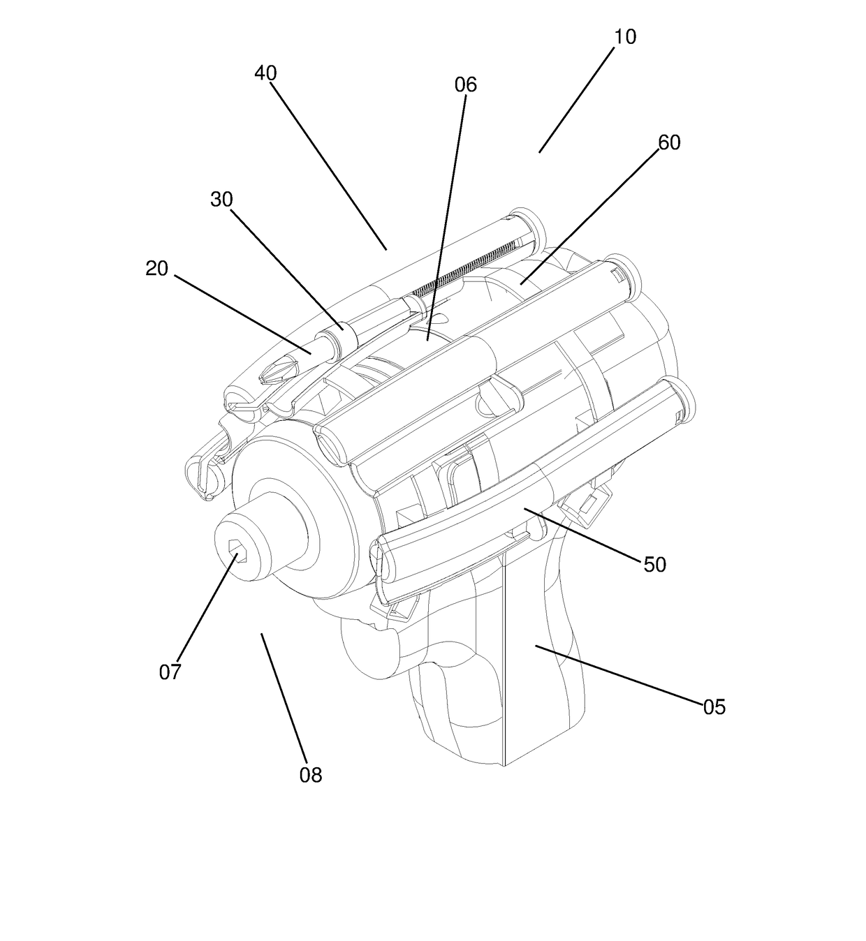
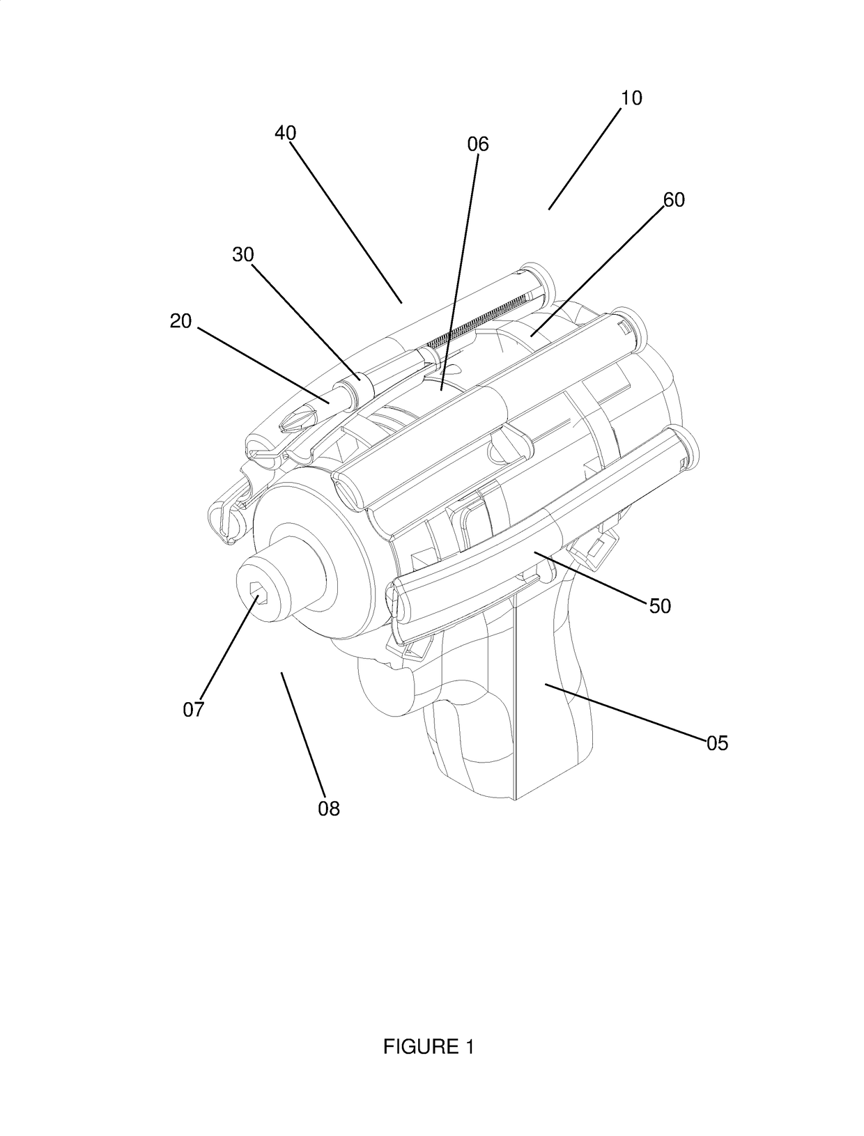
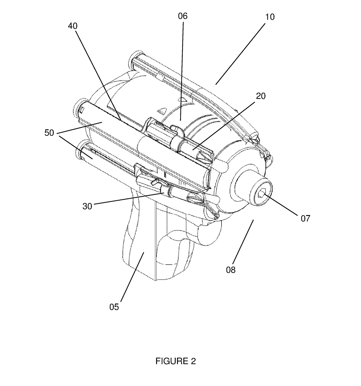
[0025]A lanyard system 10 for a piece 20 or a number of pieces 20, like a bit, should be attached to a tool 05, like an impact driver, in such a way that each piece 20 on one hand is capable of being easily inserted and used in a piece receiver 07, like a quick release connector, and on the other hand easily removed and positioned in a storage region 06 for future use. See FIGS. 1 and 2. This can be achieved for each piece 20 by attaching a piece 20 to a lanyard assembly 30 that in turn is connected to a retraction system 40. See FIGS. 1 and 2. While the following description focuses upon a lanyard system 10 with only one piece 20, the details are applicable to a lanyard system 10 with a plurality of pieces 20.

[0026]It is contemplated that tool 05 can be powered manually, electrically, pneumatically, hydraulically or a combination thereof. By illustrative example, tool 05 could be an impact driver, drill, hammer drill, nut spinner, impact wrench, reciprocating saw, paint sprayer, sa...


PUM

PropertyMeasurementUnit
lengthaaaaaaaaaa
flexibleaaaaaaaaaa
pressure sensitiveaaaaaaaaaa

Abstract

The present invention is a novel lanyard system for a piece releaseably connected to a tool by a piece receiver that includes a lanyard assembly with a two ended strap and a retraction system fixed to the tool in a storage region of the tool. In particular, one end of the strap is connected to the piece and the other strap end is connected to one end of the retraction system. The other end of the retraction system is connected to the tool. The strap is of sufficient length for the retraction system to retract a piece to the storage region after disconnection from the piece receiver. It is contemplated that the retraction system includes at least one spring (coil or helical) to cause the lanyard system to remain under tension while the piece is mounted in a piece receiver, thereby preventing or at least reducing the strap from interfering with the task at hand, the piece, the piece receiver or tool itself. The retraction system has sufficient tensional force to cause the retraction of a piece to the storage region once released from the work region of the tool.

Description

CROSS-REFERENCES TO RELATED APPLICATIONS[0001]NOT APPLICABLESTATEMENT REGARDING FEDERALL SPONSORED RESEARCH OR DEVELOPMENT[0002]NOT APPLICABLENAMES OF PARTIES TO A JOINT RESEARCH AGREEMENT[0003]NOT APPLICABLEREFERENCE TO A SEQUENCE LISTING[0004]NOT APPLICABLEBACKGROUND OF INVENTION1 Field of Invention[0005]The present invention relates generally to tools. More particularly, the present invention relates to supporting and retaining a removable piece that is used with a tool, such as impact driver, drill, hammer drill, nut spinner, impact wrench, reciprocating saw, paint sprayer, sand blaster or water blaster. The present invention is a retracting lanyard for a drill bit, screw bit, socket driver, chisel, saw blade, or nozzle. In short, the novel lanyard system of the present invention stores, tethers, retains, extends and retracts a piece that is fixed in and removed from a tool. The piece is designed to perform a task such as, but not limited to tightening, loosening, drilling, chis...

Claims


Application Information

Patent Timeline
Patent Type & Authority Applications(United States)
IPC IPC(8): B25H3/00
CPCB25H3/003B25F5/029B23B45/003B23Q3/15706B23Q3/15713B25B23/0035B25F1/00B25F1/04B25F3/00B25G1/08
Inventor BRULL, JAMES GREGORY
Owner BRULL JAMES GREGORY
Why Eureka
Try Eureka