Lint cleaner

Active Publication Date: 2017-10-05
LUMMUS INDS
View PDF0 Cites 4 Cited by
  • Summary
  • Abstract
  • Description
  • Claims
  • Application Information

AI Technical Summary

Benefits of technology

[0009]To make the degree of combing variable in

Problems solved by technology

However, many countries and merchants value the well combed, “smooth” appearance above the H.V.I. evalu

Method used


Image

  • Lint cleaner
  • Lint cleaner
  • Lint cleaner

Examples


Embodiment Construction

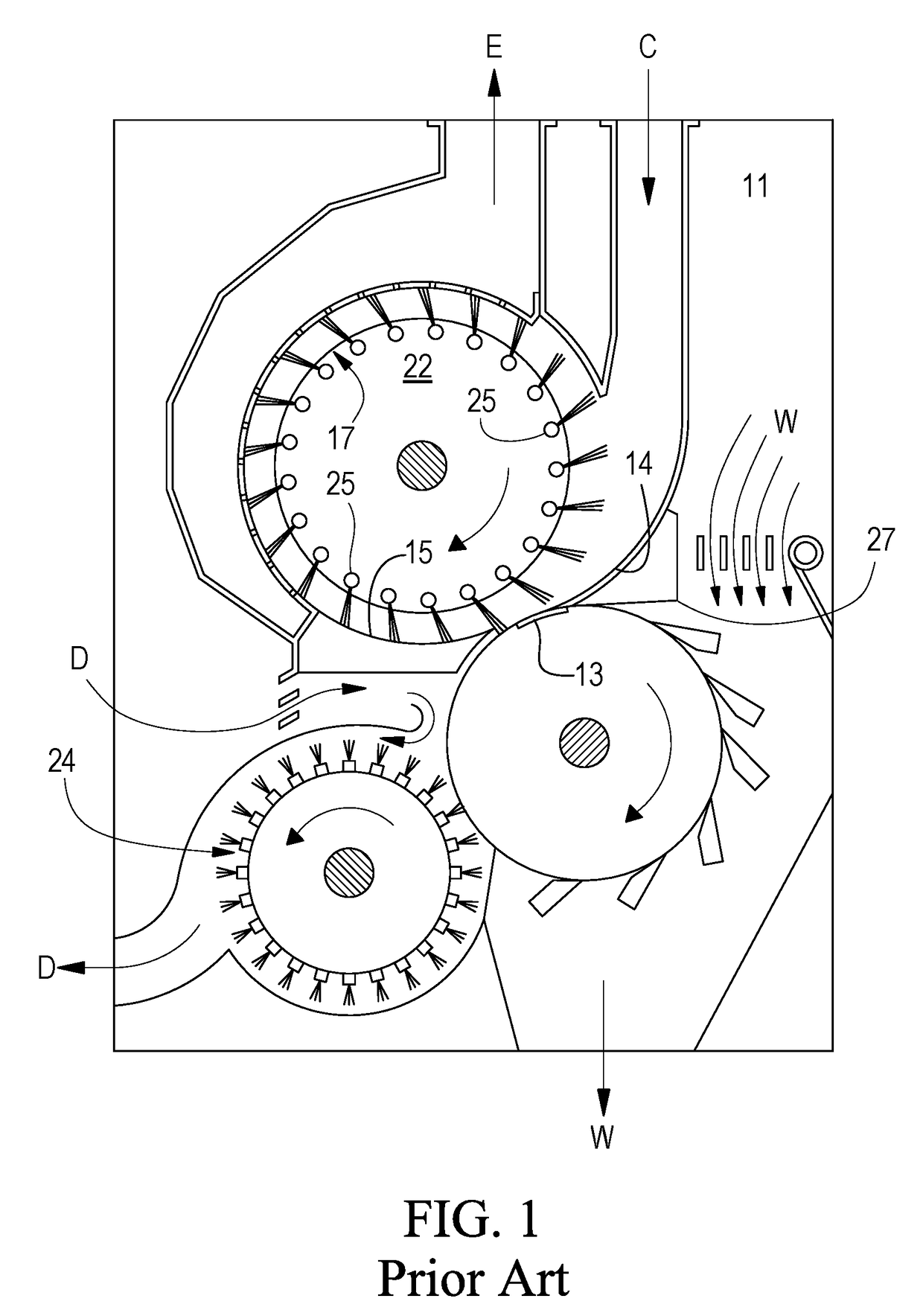
[0020]In the prior art shown in FIG. 1, the bulk of the tufts carried by an airstream flow directly across the top surface of streamer plate 14 and are abruptly whipped over the tip of the plate by the aggressive teeth 13 of cleaning cylinder 12. This action produces a minimum amount of “opening” of the lint tufts. The smaller number of entering lint tufts that are drawn into the separator cylinder 22 between the brushes move to the perforated screen surrounding cylinder 22 and are swept by the brushes around to plate 14 to also receive a minimum amount of opening.

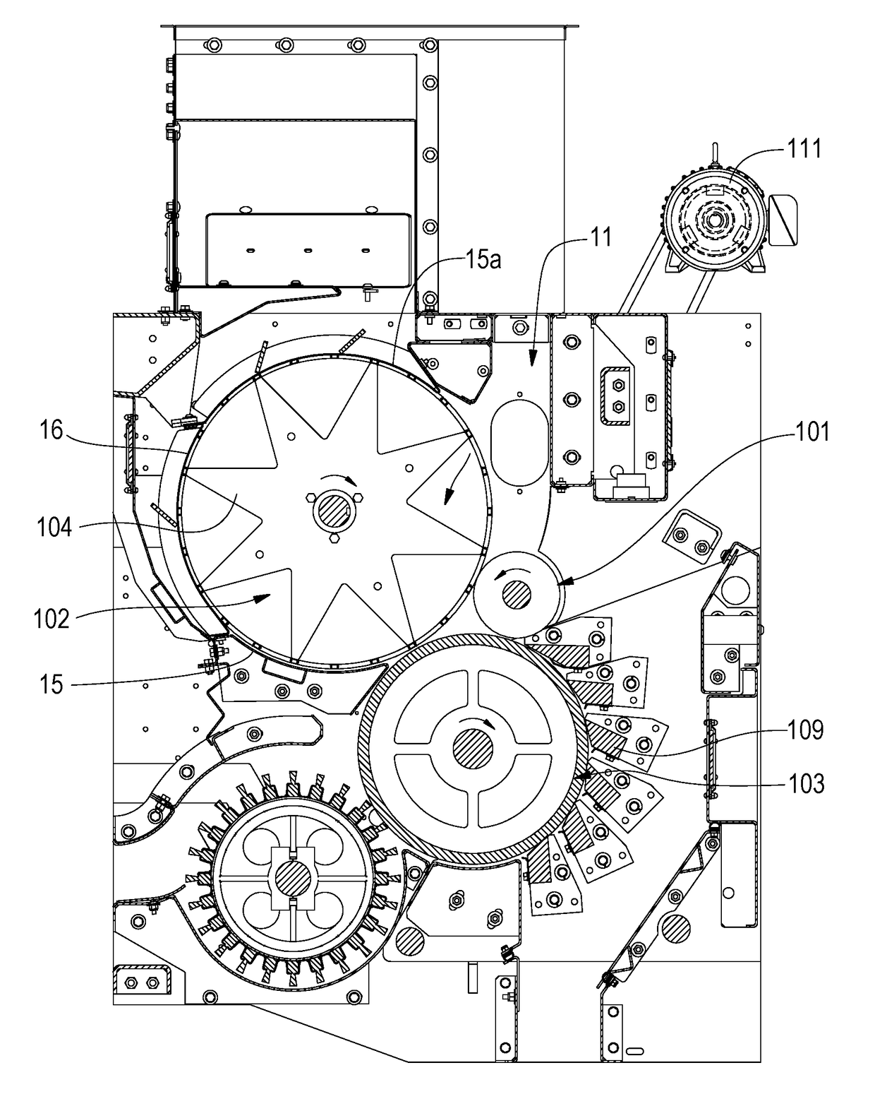
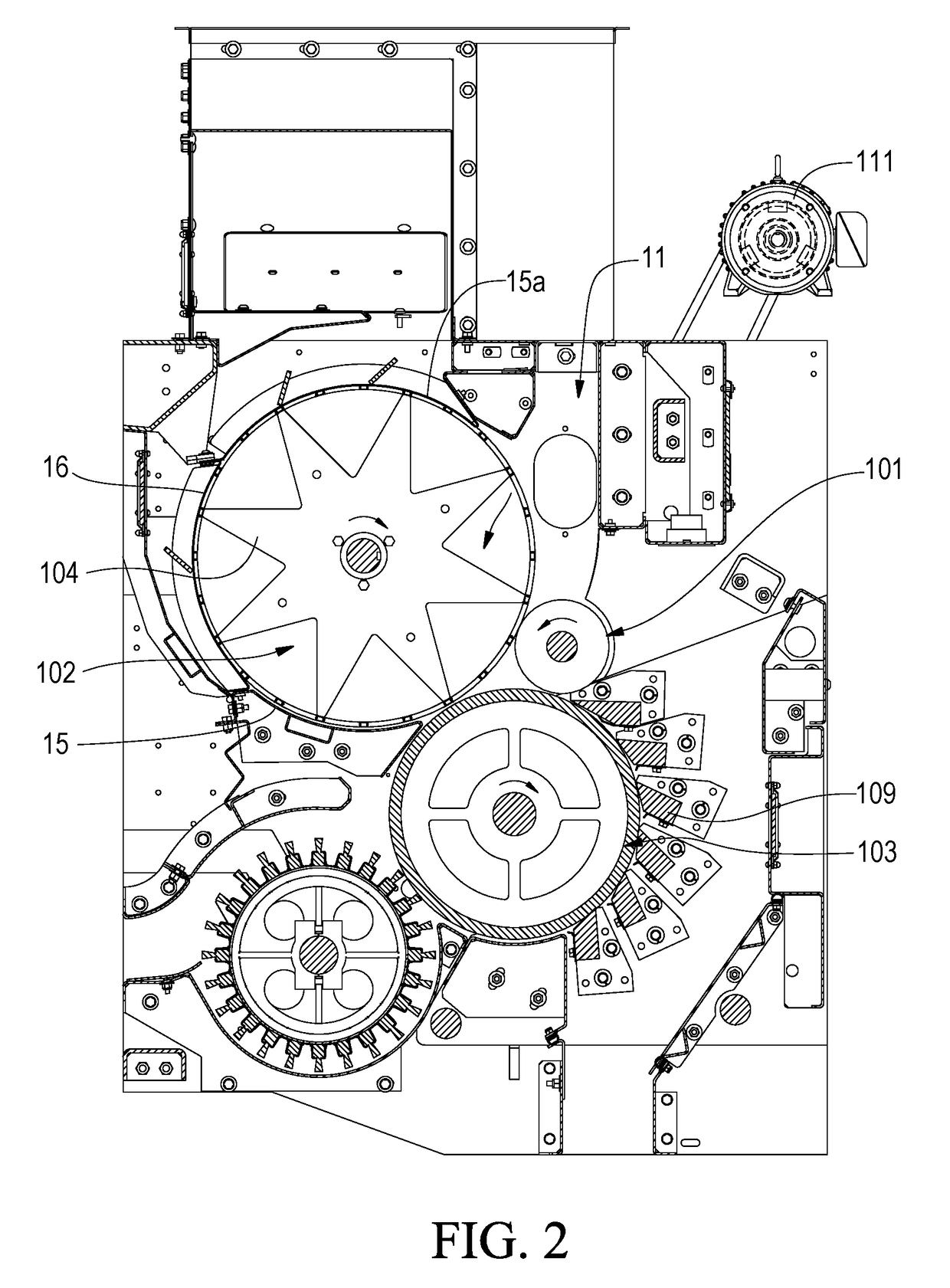
[0021]FIG. 2 is a cross section drawing of a preferred embodiment of the present invention. As the lint tufts enter the machine at duct 11 at the upper right the bulk of them are thrown against the upper surface of a slowly counter-clockwise rotating combing cylinder 101. Air duct 11 terminates adjacent an outer surface of revolving combing cylinder 101 and a stationary separator housing and delivers the majority of the tu...


PUM


Abstract

An apparatus for cleaning trash from cotton lint utilizes a combing cylinder having a plurality of teeth covering its surface and extending therefrom in a manner to release the cotton lint to a cleaning cylinder. The combing cylinder surface moves slower than the cleaning cylinder to comb the lint as it is delivered to the cleaning cylinder. Means are provided to vary the speed of the combing cylinder to match the lint processing parameters, including negating lint combing all together.

Description

BACKGROUND OF THE INVENTION[0001]The present invention relates to the field of cotton processing and represents a further improvement on the lint cleaners of U.S. Pat. No. 6,088,881 and U.S. Pat. No. 7,779,514 B2. U.S. Pat. No. 7,779,514B2 describes apparatus that reduces fiber damage by eliminating the formation of the cotton tufts into a batt, but rather, individually applies the tufts of cotton as they come from the gin stand in an airstream directly onto the teeth of the lint cleaner cleaning cylinder teeth without mechanically restraining the tufts. Such a device is for use with lint cleaners that have short, densely spaced teeth on a solid cylinder which currently are universally used in saw gins on upland cotton.[0002]Other prior methods and apparatus include those such as illustrated in U.S. Pat. No. 6,088,881, incorporated herein by reference, wherein a revolving perforated drum is used to allow air flow through the drum such that a cleaning cylinder may remove cotton fiber...

Claims


Application Information

Patent Timeline
IPC IPC(8): D01G9/06D01G9/04
CPCD01G9/04D01G9/06D01B1/04
Inventor VAN DOORN, DONALD WILLIAM
Owner LUMMUS INDS
Why Eureka
Try Eureka