Method to measure the ability of a flowing powder to electrostatically charge and measurement device

Active Publication Date: 2017-10-05
UNIV LIEGE
View PDF5 Cites 2 Cited by
  • Summary
  • Abstract
  • Description
  • Claims
  • Application Information

AI Technical Summary

Benefits of technology

The present invention provides a method and device for measuring the flowing properties of powders in a standardised manner. The temperature, pressure, and humidity at which the method is performed can be adjusted to mimic the actual conditions of where the powders will be used. The method is useful for quantifying the complex effect of humidity variations on the electric charges present in powders. The technical effects include the ability to measure powders in a reliable and consistent way, regardless of external factors, and the ability to compare measurement results from different locations and users.

Problems solved by technology

The apparition of electric charges inside a powder can produce sparks and cause explosion hazards.
In addition, the electrostatic charging during powder particle flow induces agglomeration and segregation which may cause dosage problems.
The above methods have the disadvantage that they are difficult to use in practice for all type of particles or grains and furthermore give fluctuating results.
Therefore, the results obtained with these methods are difficult to compare with triboelectric charging effects observed in devices wherein the powder is present in a more dense composition.

Method used


Image

  • Method to measure the ability of a flowing powder to electrostatically charge and measurement device
  • Method to measure the ability of a flowing powder to electrostatically charge and measurement device
  • Method to measure the ability of a flowing powder to electrostatically charge and measurement device

Examples


example 1

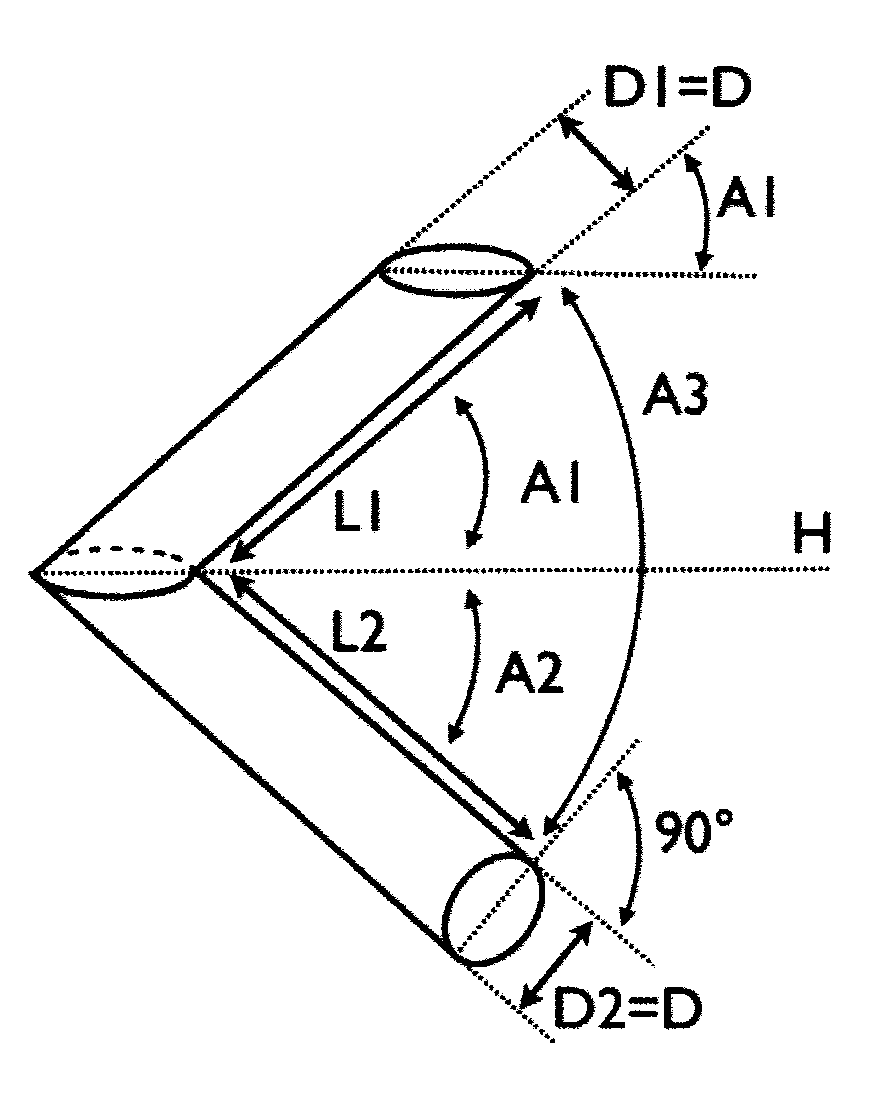
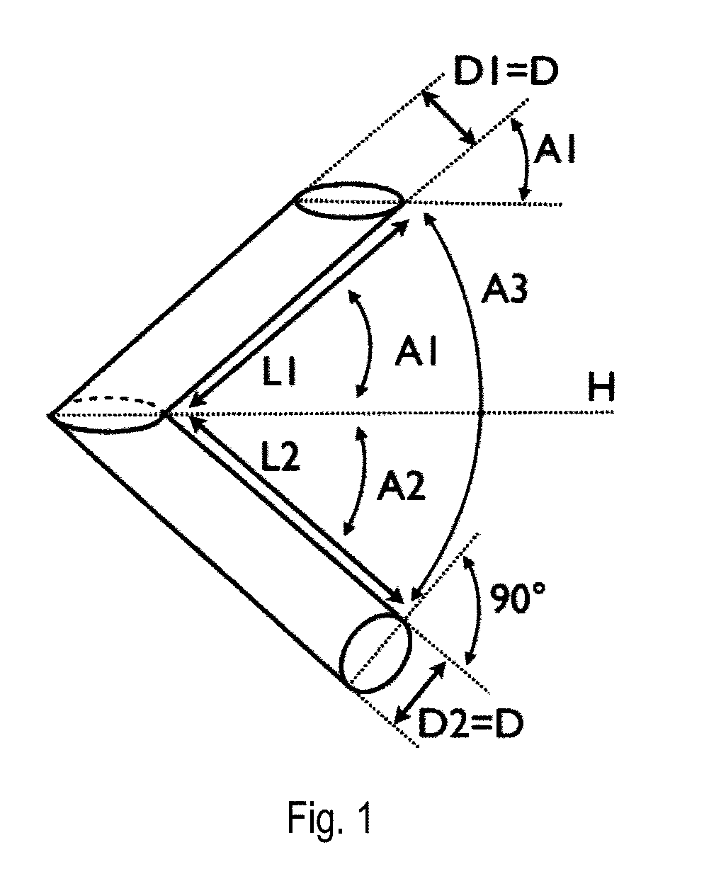
[0043]In this example the influence of the tube length L as in FIG. 1 was investigated. The measurements with the glass beads were performed with different tube length L. The V-tube used to perform these measurements was made of stainless steel 316L. The tube angle has been fixed at A=45′ and the tube internal diameter at D=47 mm. The vibration frequency was fixed at 100 Hz. The measurements were performed in a device as illustrated in FIG. 2 wherein 150 g of the glass powder was gently poured into the inlet opening of the upper part during a period of about 15 seconds. The results are presented in FIG. 4 which presents the absolute value of the charge density inside the sample after the flow in the V-tube as a function of the Length L. From the plot it may be concluded that the amount of charge inside the powder increases with the tube length L. Therefore, a V-tube formed by two long tubes will give better results. However, practically, a long V-tube is difficult to use in a labora...

example 2

[0044]Example 1 was repeated except that instead of varying the length L the internal diameter D of the tube was varied. The tube length L was fixed at 350 mm. The results are presented in FIG. 5 which presents the absolute value of the charge density inside the sample after the flow in the V-tube as a function of the internal tube diameter D. From the plot it may be concluded that the amount of charge inside the powder decreases with the internal tube diameter D. Therefore, a V-tube formed by two tubes with a small diameter will give better results. However, practically, a V-tube with a very small diameter is difficult to fill with the powder, in particular with a cohesive powder. Suitably a tube internal diameter of between D=40 mm and D=60 mm is therefore chosen.

example 3

[0045]Example 1 was repeated except that instead of varying the length L the Angle A was varied. The tube length has been fixed at L=350 mm and the tube internal diameter at D=47 mm. The results are presented in FIG. 6 which presents the absolute value of the charge density inside the sample after the flow in the V-tube as a function of the of the angle A. FIG. 6 illustrates reproducibility of the method at different angles.


PUM


Abstract

A method and measurement device for measuring the ability of a flowing powder to electrostatically charge comprising a conduit comprised of a straight upper part fluidly connected to a straight lower part, the upper part being positioned at a first angle to the horizontal and the lower part being positioned at a second angle to the horizontal and wherein upper and lower part are positioned at a third angle relative to each other defining a bend at the intersection of the upper and lower part, wherein the upper part is provided with a supply opening for the powder and the lower part is provided with a discharge opening to discharge the powder and a faraday cup is connected to an electrometer positioned relative to the discharge opening to receive powder the from the conduit.

Description

BACKGROUND OF THE INVENTION[0001]The invention is directed to a method to measure the ability of a flowing powder to electrostatically charge by allowing the powder to flow under the influence of gravity and measuring the electrostatic charge of the powder. The invention is also directed to a measurement device to measure the ability of a flowing powder to electrostatically charge.[0002]It is well known in the art that electrostatic charges are created inside a powder during a flow. This apparition of electric charges is due to the triboelectric effect, which is a charge exchange at the contact between two solids. During the flow of a powder inside a device, such as a mixer, a silo or a conveyor, the triboelectric effect takes place at the contact between the solid powder particles and at the contact surface between these particles and the device. In particular, triboelectric effect takes place when two particles are sliding on each other or when a particle is sliding on a surface o...

Claims


Application Information

Patent Timeline
IPC IPC(8): G01N27/60
CPCG01N27/60
Inventor LUMAY, GEOFFROYSCHOCKMEL, JULIENVANDEWALLE, NICOLASBOSCHINI, FREDERIC
Owner UNIV LIEGE
Why Eureka
Try Eureka