Display Device And Display Module

a display module and display device technology, applied in semiconductor devices, spectral modifiers, lighting and heating apparatus, etc., can solve the problems of reducing display quality, limiting light, and damage to vision, so as to reduce radiation, not decrease the display effect, and reduce the blue energy

Inactive Publication Date: 2017-10-05
WUHAN CHINA STAR OPTOELECTRONICS TECH CO LTD
View PDF4 Cites 10 Cited by
  • Summary
  • Abstract
  • Description
  • Claims
  • Application Information

AI Technical Summary

Benefits of technology

[0014]Comparing to the conventional art, in the display module provided by the present invention, through right shifting the peak wavelength of the blue wave band emitted from the blue LED chip to about 460 nm in order to realize the low blue energy so as to decrease the radiation. At the same time, in order to not decrease the display effect (generally including color saturation, NTSC color gamut and if the color is shifted and so on), designing a colour filter, the transmittance of the blue light of the colour filter is less than 7%, the peak wavelength of the blue light is in a range of 440-450 nm. The display module cannot only decrease the energy of the blue wave band, but also ensure the display effect, Besides, the display module also adds a certain amount of red phosphors in order to make the energy distribution ratios of red / green / blue three colors of the emission light emitted from the display device to closer, that is, closed to the natural light.

Problems solved by technology

In the lights emitted from the display device, unavoidably, more blue light is contained.
Medical research indicates that the light in the blue band has a higher energy, and will cause the damage of the vision when the human eye contact chronically.
However, the drawback of the above method is that the display of the blue color will be distorted, and the whole picture will exist a serious yellow shift phenomenon, the display quality is dramatically decreased.
Because the visible light emitted by the backlight has a higher energy at the blue band, the low blue damage of the display device becomes a problem that cannot be ignored.

Method used


Image

  • Display Device And Display Module
  • Display Device And Display Module
  • Display Device And Display Module

Examples


Embodiment Construction

[0020]The following content combines with the drawings and the embodiment for describing the present invention in detail. It is obvious that the following embodiments are only some embodiments of the present invention. For the person of ordinary skill in the art without creative effort, the other embodiments obtained thereby are still covered by the present invention.

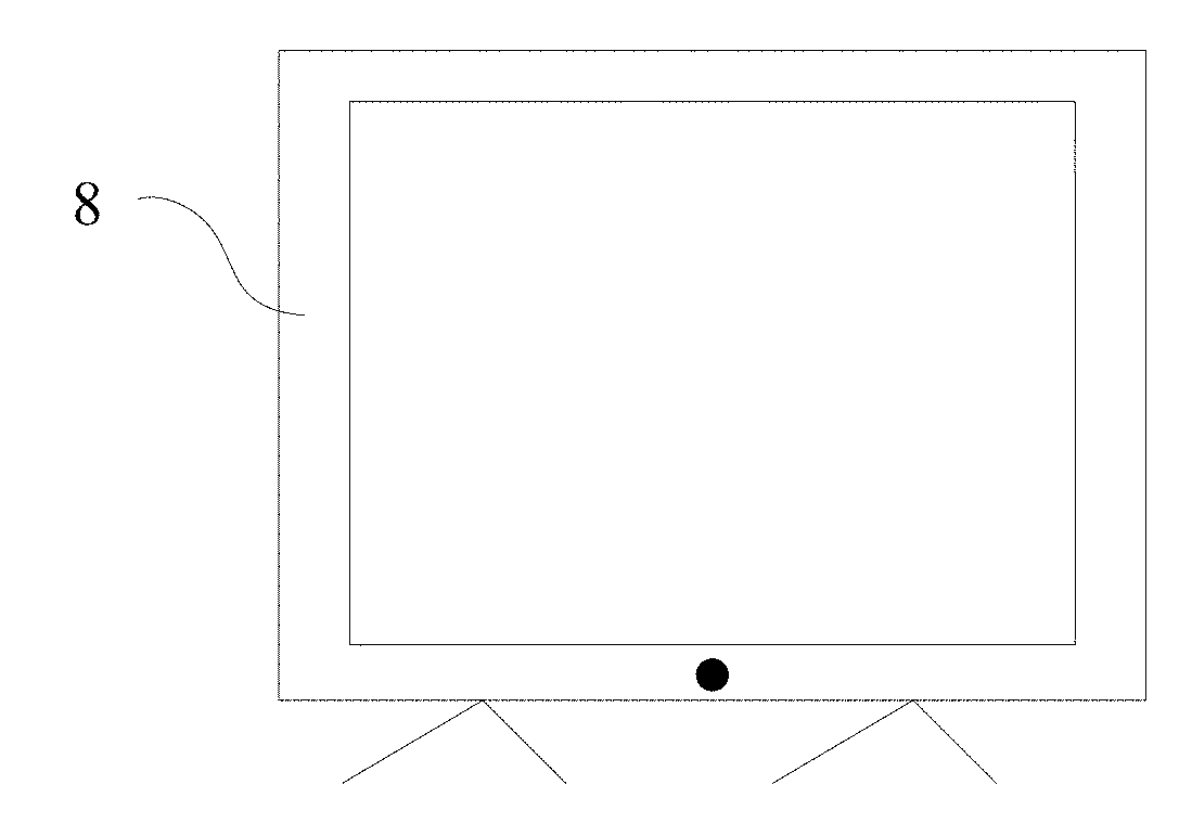
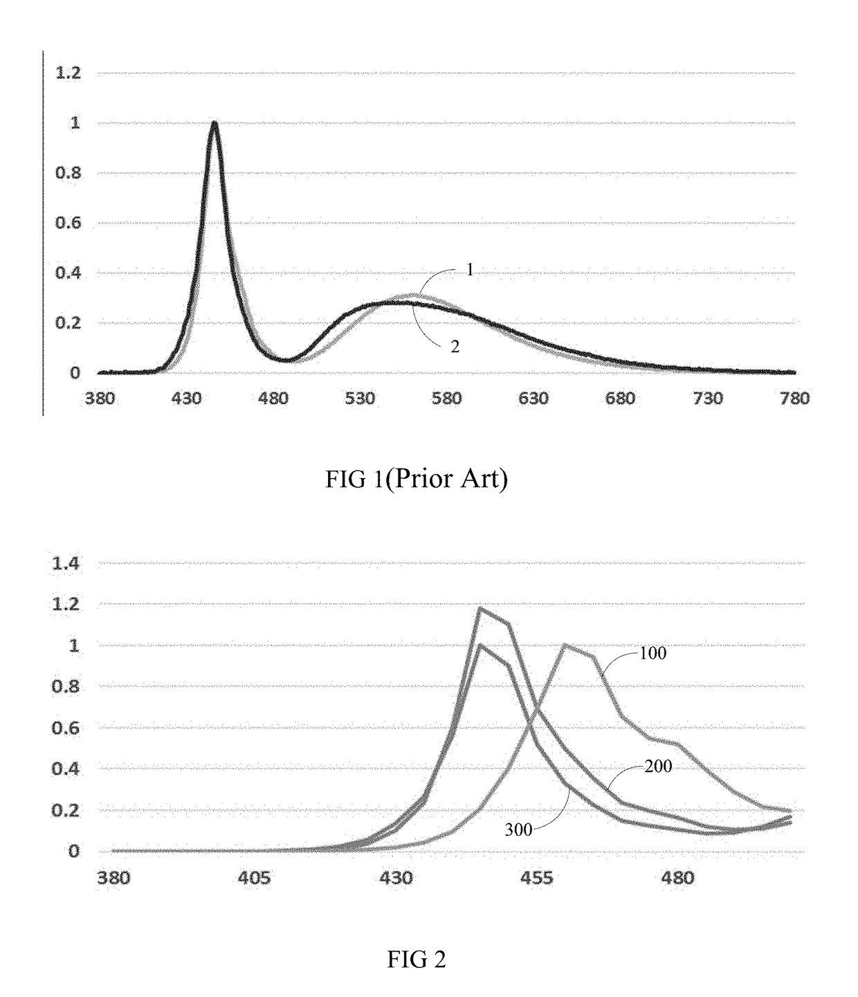
[0021]The embodiment of the present invention provides a display module, and the display module includes a blue LED chip, a yellow phosphor layer and a colour filter. Wherein, in order to decrease the energy of the blue light emitted from the blue LED chip, the embodiment of the present invention right shifts a peak wavelength of the blue light emitted from the blue LED chip, adjusting to about 460 nm. Preferably, the peak wavelength of the blue light emitted from the blue LED chip is in a range of 460±5 nm. Preferably, the peak wavelength of the blue light emitted from the blue LED chip is in a range of 460±2 nm, or th...


PUM


Abstract

A display device and a display module. The display module includes: a blue LED chip, a yellow phosphor layer and a colour filter. A peak wavelength of a blue light emitted from the blue LED chip is in a range of 460±5 nm. The blue LED chip excites the yellow phosphor layer to emit a white light. The colour filter is disposed outside the yellow phosphor layer, and the white light emitted irradiates on colour filter. Through right shifting the peak wavelength of the blue band emitted from the blue LED chip to about 460 nm to realize the low blue energy and decrease the radiation. The transmittance of blue light of the colour filter is less than 7%, the transmission peak wavelength of blue light is in a range of 440-450 nm. The display module can decrease the energy of the blue band and ensure the display effect.

Description

BACKGROUND OF THE INVENTION1. Field of the Invention[0001]The present invention relates to a technology field of display device backlight and light filtering, and more particularly to a display device and a display module.2. Description of Related Art[0002]In the lights emitted from the display device, unavoidably, more blue light is contained. Medical research indicates that the light in the blue band has a higher energy, and will cause the damage of the vision when the human eye contact chronically. The damage to the growing and developing people such as infants, young is more obvious in this aspect. The way to decrease the blue energy on the market is to attach a blue filter or decrease the blue energy through an APP (application). However, the drawback of the above method is that the display of the blue color will be distorted, and the whole picture will exist a serious yellow shift phenomenon, the display quality is dramatically decreased. Accordingly, how to maintain displayin...

Claims


Application Information

Patent Timeline
Patent Type & Authority Applications(United States)
IPC IPC(8): H01L33/50H01L33/58F21V9/08
CPCH01L33/50H01L33/58F21V9/08H01L33/502H01L33/505H01L33/44H01L33/504
Inventor LI, DE-JIUNPENG, HAIBOCHEN, LINGYAN
Owner WUHAN CHINA STAR OPTOELECTRONICS TECH CO LTD
Why Eureka
Try Eureka