Robust and High Current Smart-Plug

a smart plug, high-current technology, applied in the integration of power network operation systems, coupling device connections, sustainable buildings, etc., can solve the problems of requiring corresponding circuit complexity, and achieve the effect of measuring and saving energy usag

Active Publication Date: 2017-10-05
COMPUTIME LIMITED
View PDF2 Cites 6 Cited by
  • Summary
  • Abstract
  • Description
  • Claims
  • Application Information

AI Technical Summary

Benefits of technology

[0005]An aspect supports a smart plug that is partitioned into a plurality of printed circuit boards (PCBs) in accordance with an emb

Problems solved by technology

However, these capabilities typically require corresponding circuit complexity while supplyin

Method used


Image

  • Robust and High Current Smart-Plug
  • Robust and High Current Smart-Plug
  • Robust and High Current Smart-Plug

Examples


first embodiment

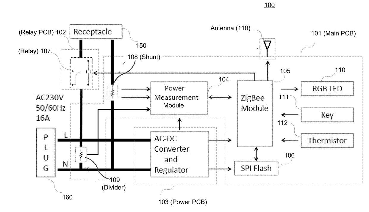
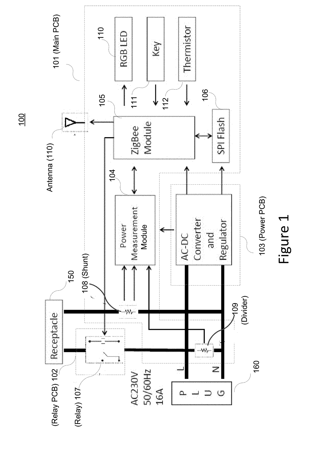
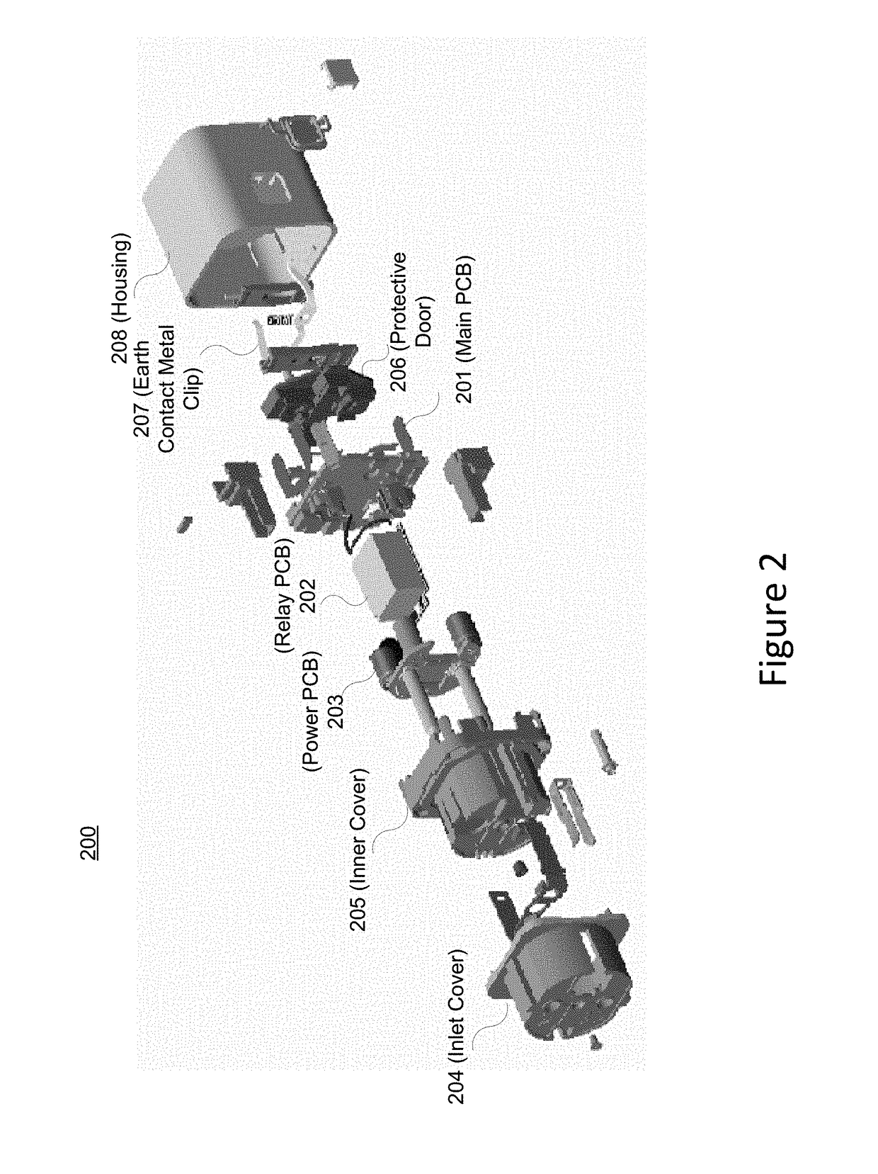
[0066]With a first embodiment, to minimize size, a smart plug structure is partitioned into multiple PCBs such as main, power, and relay type PCBs with copper foils. Assembly of these PCBs may be constructed in a three-dimensional fashion as shown in FIG. 4.

second embodiment

[0067]With a second embodiment, to minimize power dissipation (and thus the temperature rise within a smart plug) the smart plug may comprise a low contact resistance relay and thick copper foils that are electrically connected on top of PCB traces in both neutral (N) and live (L) lines to reduce resistance of the load current path.

third embodiment

[0068]With a third embodiment, copper foil may be used to connect a current-sense resistor in neutral plug or socket contact metal in one side and metal pin on the other side as shown in FIG. 5.


PUM


Abstract

A smart plug that is partitioned into a plurality of printed circuit boards (PCBs) in a three dimensional manner to reduce its size. Aspects consider the effect of the possible increased internal temperature as the size of the smart plug is reduced. For example, thick metal foils connect various components of a smart plug to reduce heat dissipation within the smart plug. Also, a metal foil may transfer heat from contact metal on a PCB to a side wall of a plastic housing of the smart plug. The smart plug may comprise a computing device that obtains information identifying the attached electrical device and accesses device data about the time duration during which the attached electrical device exhibits transient characteristics. The computing device then uses the accessed data to effectively control the attached electrical device.

Description

[0001]This patent application claims priority to U.S. provisional patent application Ser. No. 62 / 317,899 entitled “Robust and High Current Smart-Plug” filed on Apr. 4, 2016, which is hereby incorporated by reference in its entirety.TECHNICAL FIELD[0002]Aspects of the disclosure relate to a smart plug that provides electrical power to an attached electrical device such as an appliance.BACKGROUND OF THE INVENTION[0003]A smart plug is typically a device that plugs right into an ordinary outlet and has its own outlet. An appliance may be plugged into the smart plug's outlet to obtain enhancements with respect to the ordinary electrical outlet. For example, a smart plug may, via an app, enable a user to actively control it, automate it according to a time schedule, or trigger it from another electronic system.[0004]Smart plugs may be a versatile building block of the smart home, with numerous uses for security, convenience, and energy savings. However, these capabilities typically requir...

Claims


Application Information

Patent Timeline
IPC IPC(8): H02J13/00H05K1/14H05K1/02
CPCH02J13/0075H05K1/144H05K1/0201H01R2103/00H01R13/6658H01R24/30H01R24/78H05K1/0263H05K1/11H05K3/284H05K2201/10272Y04S20/242Y04S40/126G01R21/06H02J13/00026H02J13/0005Y02B70/30Y02B90/20Y04S20/00G01R21/133
Inventor CHAN, DICK KWAILAM, KAM WAIZHENG, JZSHUM, WAI YINJUDGE, BRENTON JAMESYILMAZ, HAMZAYEUNG, PATRICKWU, WAI MING
Owner COMPUTIME LIMITED
Why Eureka
Try Eureka