Front flange of a rotary electrical machine, and rotary electrical machine comprising a flange of this type

Inactive Publication Date: 2017-10-05
VALEO EQUIP ELECTRIC MOTEUR
View PDF3 Cites 3 Cited by
  • Summary
  • Abstract
  • Description
  • Claims
  • Application Information

AI Technical Summary

Benefits of technology

[0022]The objective of the present inve

Problems solved by technology

These braces are subjected to substantial forces because of the presence of the tensioning roller

Method used


Image

  • Front flange of a rotary electrical machine, and rotary electrical machine comprising a flange of this type
  • Front flange of a rotary electrical machine, and rotary electrical machine comprising a flange of this type
  • Front flange of a rotary electrical machine, and rotary electrical machine comprising a flange of this type

Examples


Embodiment Construction

)

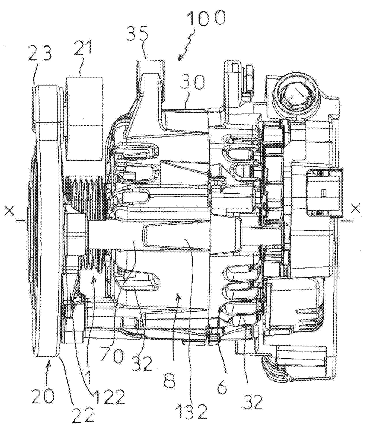
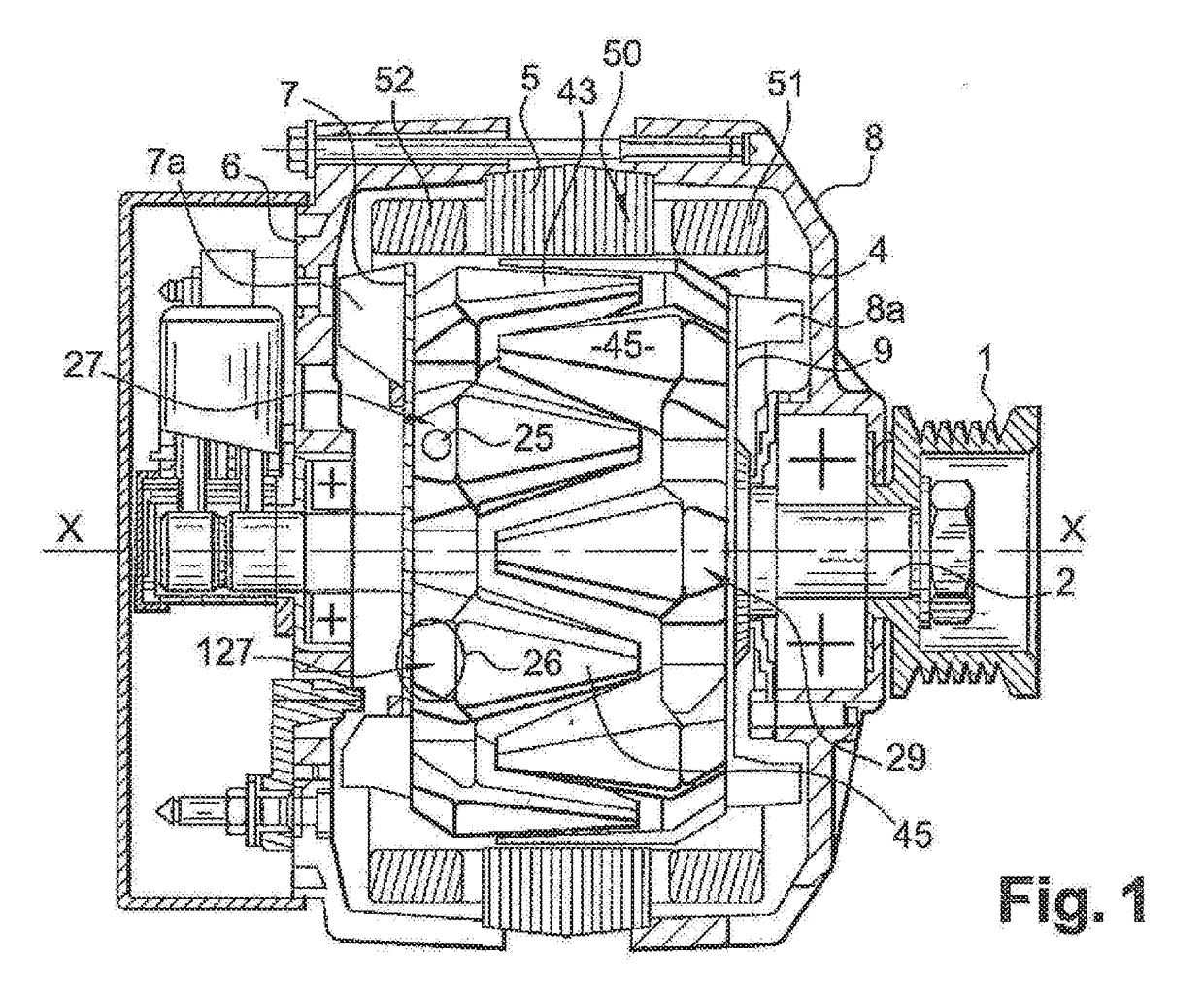
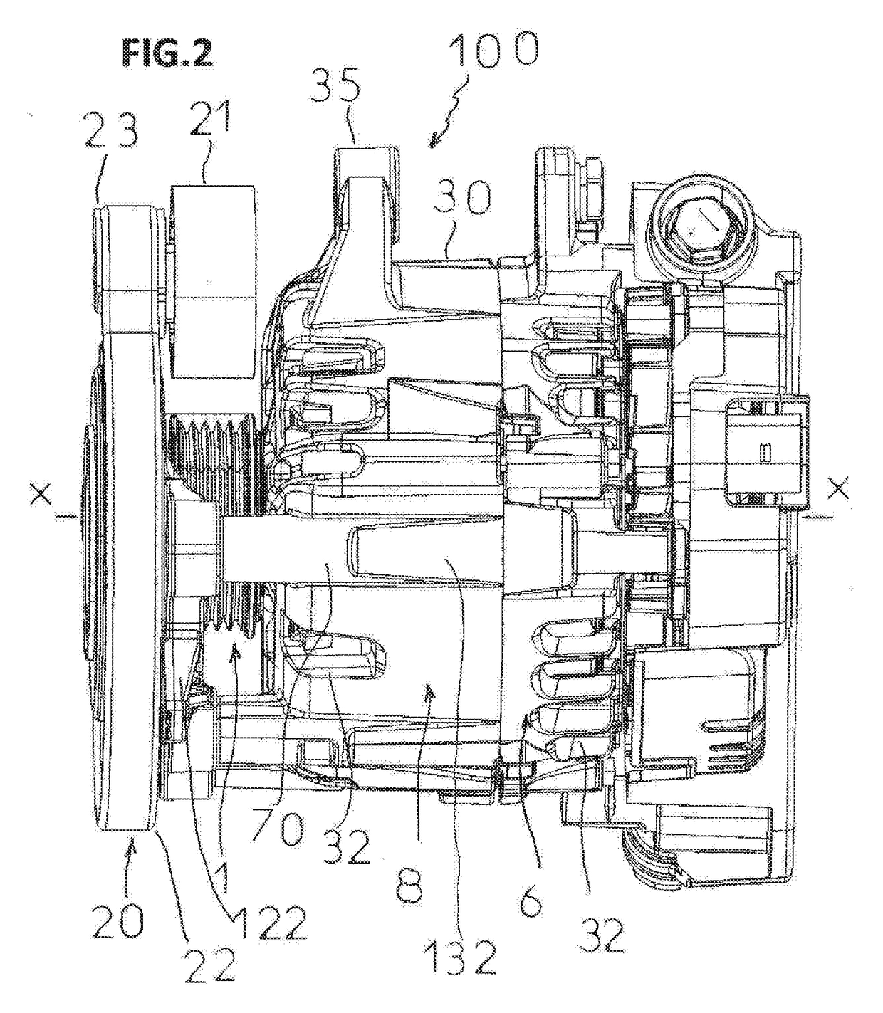
[0068]In the figures, elements which are identical or similar to those in FIG. 1 will be allocated the same reference numbers, and for the sake of simplicity FIGS. 2 to 5 represent only the elements which are necessary for understanding of the invention.

[0069]For the other internal elements of the machine, i.e. rotor shaft, ball bearing, stator, rotor, fans, brush-holder, sensor-holder, inverter, rectifier bridge, as applicable, reference will be made to the prior art and to FIG. 1, in the knowledge that the rotor of the machine can be a rotor with claws, a rotor with projecting poles, or a rotor with permanent magnets, and the stator winding can have concentric coils, as for example in document WO 2007 / 031679, or an undulating winding as for example in document EP 0 881 742. In FIGS. 2 to 5, the rotary electrical machine 100 is an alternator-starter with internal ventilation of the type in FIG. 1 and that described for example in document WO 01 / 69762 or document FR A 2 745 444, wi...


PUM


Abstract

The front flange made of mouldable material of a rotary electrical machine with a pulley (1) for receipt of a belt comprises at least two projecting braces (70) with axial orientation obtained by moulding of its outer periphery, and designed for securing of a support of at least one body, such as a belt tensioning roller, the braces (70) each comprising laterally at least one hollow (71).

Description

CROSS-REFERENCE TO RELATED APPLICATIONS AND CLAIM TO PRIORITY[0001]This application is related to Patent Application No. 1652723 filed Mar. 30, 2016 in France, the disclosure of which is incorporated herein by reference and to which priority is claimed.FIELD OF THE INVENTION[0002]The present invention relates to a front flange made of mouldable material of a rotary electrical machine with a pulley for receipt of a belt.[0003]The present invention also relates to a rotary electrical machine with a pulley for receipt of a belt comprising a flange of this type.BACKGROUND OF THE INVENTION[0004]FIG. 1, which is a view in axial cross-section identical to FIG. 1 of document WO 2007 / 031679 shows schematically a conventional rotary electrical machine in the form of a reversible alternator, known as an alternator-starter, described for example in documents WO 01 / 69762 or FR A 2 745 444.[0005]This machine comprises a housing 6, 8 made of mouldable material, such as housing made of aluminium or...

Claims


Application Information

Patent Timeline
IPC IPC(8): H02K7/10
CPCH02K7/1008H02K5/04H02K7/10H02K5/15
Inventor PACCOU, GORDAINE
Owner VALEO EQUIP ELECTRIC MOTEUR
Why Eureka
Try Eureka