Image forming apparatus

a technology of forming apparatus and forming plate, which is applied in the direction of inking apparatus, printing mechanism, printing, etc., can solve the problems of degrading printing quality, degrading printing quality, and degrading printing quality, so as to increase the duty ratio, and high quality

Active Publication Date: 2017-10-12
COPYER
View PDF2 Cites 0 Cited by
  • Summary
  • Abstract
  • Description
  • Claims
  • Application Information

AI Technical Summary

Benefits of technology

[0016]The upstream-side and downstream-side drive sources may each be a PWM controlled DC motor, and the controller may change a duty ratio of the DC motor in PWM control to adjust the drive amounts of the first and the second upstream-side drive sources. In this case, the controller may increase the duty ratio of the first upstream-side drive source and reduces the second upstream-side drive source by an increase in the duty ratio of the first upstream-side drive source.
[0017]According to the present invention, when adjusting a drive amount of the drive source of one of the first and second conveying units, the controller also adjusts a drive amount of the drive source of the other one thereof according to the adjustment amount of the drive source of the one conveying unit, thereby making it possible to prevent the film-shaped medium and ink ribbon from excessively advancing at image formation by the image forming unit, whereby a high quality image can be formed on the film-shaped medium.

Problems solved by technology

Such pitch unevenness is gradation appearing irrelevant to printing data and may thus cause degradation in printing quality.
Such slippage may produce an image missing part (image skipping) on the transfer film 46, which may degrade printing quality as the pitch unevenness does.
However, when the back tension with respect to the ink ribbon 41 is excessively reduced, the slippage occurs in the ink ribbon 41 due to the tension force of the film conveying motor Mr5 that drives the film conveying roller 49, which may degrade printing quality.
In such simple drive amount determination processing, a computation load on the CPU is reduced, whereas repetition of the simple drive amount determination processing many times may cause cumulative error.

Method used


Image

  • Image forming apparatus
  • Image forming apparatus
  • Image forming apparatus

Examples


Embodiment Construction

[0039]Hereinafter, an embodiment in which the present invention is applied to a printer that prints and records text or images on a card while performing magnetic or electric information recording on the card will be described.

1. Configuration

1-1. System Configuration

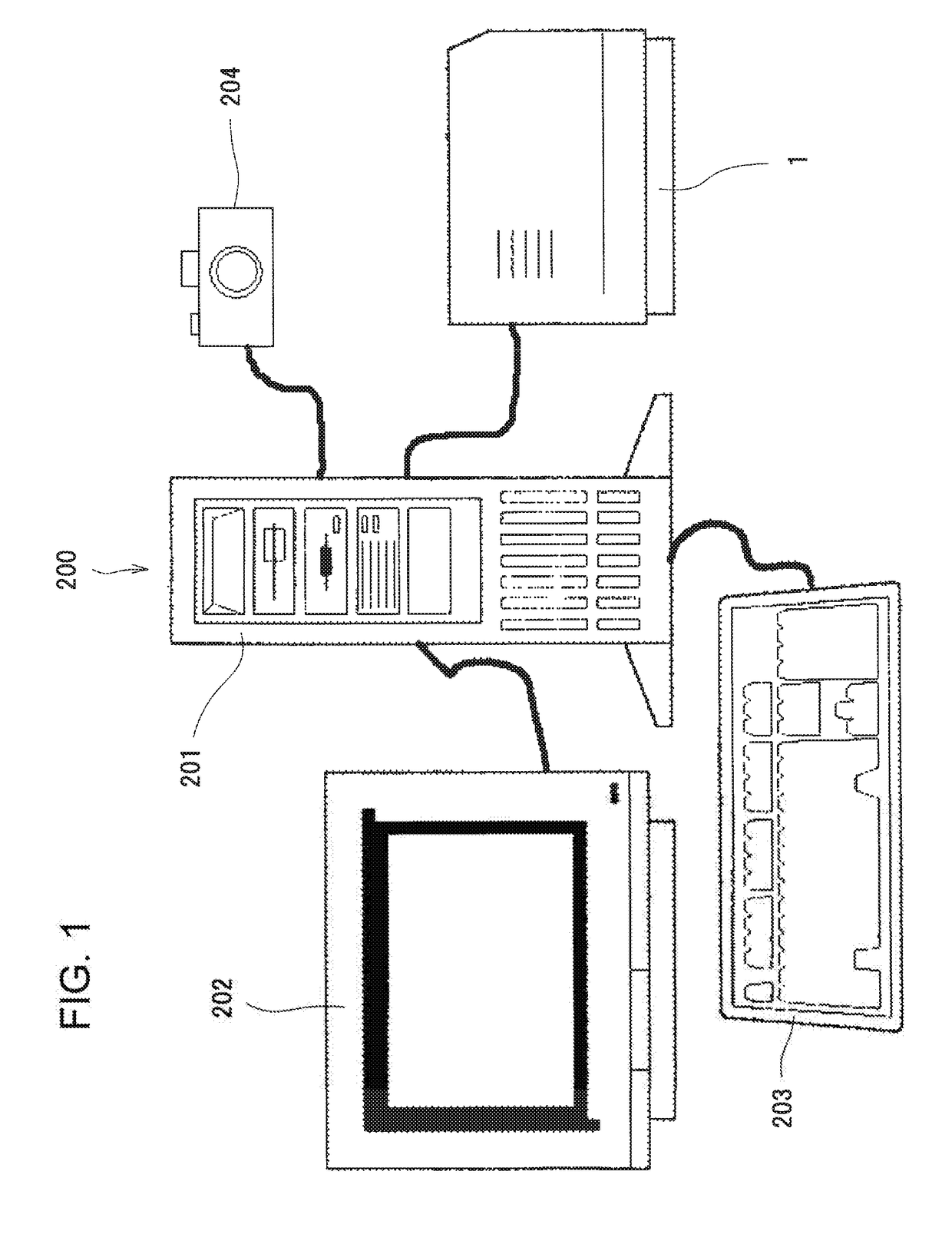
[0040]As illustrated in FIGS. 1 and 15, a printer 1 according to the present embodiment constitutes a part of a printing system 200. That is, the printing system 200 roughly includes a host device 201 (for example, host computer such as a personal computer) and the printer 1.

[0041]The printer 1 is connected to the host device 201 through an unillustrated interface, and thus an operator can instruct the printer 1 to perform recording operation or the like by transmitting printing data or magnetic or electric recording data to the printer 1 through the host device 201. The printer 1 has an operation panel section (operation display section) 5 (see FIG. 15), and thus an operator can instruct the recording operation not onl...


PUM


Abstract

In order to provide an image forming apparatus capable of forming a high quality image on a film-shaped medium, the present printer includes an image forming section B1 that forms an image on a transfer film using an ink ribbon, a film conveying mechanism that has a motor Mr4 and conveys the transfer film while applying a tension thereto, an ink ribbon conveying section that has a motor Mr3 and conveys the ink ribbon while applying a tension thereto, and a control section that controls the image forming section B1, motor Mr3, and motor Mr4. When adjusting the drive amount of one of the motors Mr3 and Mr4, the control section also adjusts the drive amount of the other one thereof according to the adjustment amount of the one motor.

Description

BACKGROUND OF THE INVENTIONField of the Invention[0001]The present invention relates to an image forming apparatus and, particularly, to an image forming device that forms an image on a film-shaped medium by using an ink ribbon.Description of the Related Art[0002]There is widely known an image forming apparatus that forms on an image on a film-shaped transfer medium. For example, such an image forming apparatus adopts an indirect printing system that forms an image (mirror image) on a transfer medium using an ink ribbon and then transfers the image formed on the transfer medium onto a surface of a printing medium such as a card or a disk.[0003]In such an apparatus, in an image forming section thereof, a heating element constituting a thermal head is used to heat an ink ribbon and a transfer medium conveyed while being nipped between a platen roller and the thermal head from the ink ribbon side according to printing data, and thereby an image is formed on the transfer medium. Nowaday...

Claims


Application Information

Patent Timeline
Patent Type & Authority Applications(United States)
IPC IPC(8): B41J2/325
CPCB41J2/325B41J15/046B41J29/393B41J33/34B41J33/36B41J11/42B41J17/04B41J17/00
Inventor AIHARA, YUICHI
Owner COPYER
Why Eureka
Try Eureka