Lubrication mechanism for bearing of vehicle electric motor

a technology of electric motor and lubrication mechanism, which is applied in the direction of mechanical energy handling, mechanical apparatus, cooling/ventilation arrangement, etc., can solve problems such as complex construction, and achieve the effect of reducing the duty ratio of electric oil pumps, preventing wear and galling of bearings

Active Publication Date: 2020-10-29
TOYOTA JIDOSHA KK
View PDF0 Cites 2 Cited by
  • Summary
  • Abstract
  • Description
  • Claims
  • Application Information

AI Technical Summary

Benefits of technology

[0017]When the temperature of the vehicle electric motor becomes high, in general, a load applied to the bearing and / or a rotational speed of the bearing becomes high. In the lubrication mechanism according to the fifth aspect of the invention, the electric oil pump is controlled such that the duty ratio of the electric oil pump is increased with increase of the temperature of the vehicle electric motor, whereby the flow rate of the oil discharged from the electric oil pump is increased and the flow rate of the oil supplied to the bearing is increased when the temperature of the vehicle electric motor is increased. Therefore, it is possible to restrain wear and galling of the bearing.

Problems solved by technology

By the way, in the lubrication mechanism for lubrication of the bearing, which is disclosed in the Patent Document 1, there is a problem that the construction is complicated, for example, due to the duplex structure of the rotor shaft.

Method used


Image

  • Lubrication mechanism for bearing of vehicle electric motor
  • Lubrication mechanism for bearing of vehicle electric motor
  • Lubrication mechanism for bearing of vehicle electric motor

Examples


embodiment

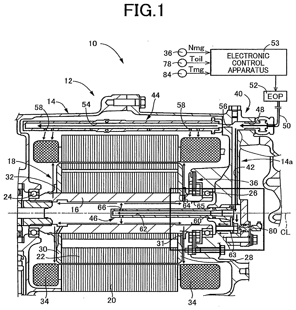
[0023]FIG. 1 is a cross sectional view of a vehicle electric motor 12 according to the embodiment of the invention, which is to be provided in a vehicle driving apparatus 10. The electric motor 12 is disposed inside a housing 14 as a non-rotary member. The electric motor 12 includes a rotor 18 and a stator 20 that is disposed radially outside the rotor 18.

[0024]The rotor 18 includes a rotor shaft 16 and a rotor core 22 fixed onto an outer circumferential surface of the rotor shaft 16.

[0025]The rotor shaft 16 has a tubular shape, and is rotatably held at its axially opposite end portions by the housing 14 through a pair of bearings 24, 26 that are provided on the axially opposite end portions of the rotor shaft 16. Thus, the rotor shaft 16 is rotatable about an axis CL.

[0026]The rotor core 22 is fixed onto the outer circumferential surface of the rotor shaft 16 so as to be unrotatable relative to the rotor shaft 16. The rotor core 22 has a tubular shape, and is constituted by a plura...


PUM


Abstract

A lubrication mechanism for supplying oil to a bearing of a vehicle electric motor that includes the bearing, a housing, a stator and a rotor having a rotor shaft rotatably held by the housing through the bearing. The housing defines an oil passage to which oil discharged from an oil pump is to be supplied. The oil passage and the bearing are located on respective opposite sides of a wall of the housing. The lubrication mechanism includes: a bolt hole passing through the wall; and a bolt engaged in the bolt hole.

Description

[0001]This application claims priority from Japanese Patent Application No. 2019-082350 filed on Apr. 23, 2019, the disclosure of which is herein incorporated by reference in its entirety.FIELD OF THE INVENTION[0002]The present invention relates to a lubrication mechanism for supplying oil to a bearing rotatably supporting a rotor shaft of a vehicle electric motor.BACKGROUND OF THE INVENTION[0003]There is known a lubrication mechanism for supplying oil to a bearing of a vehicle electric motor that includes the bearing, a stator and a rotor having a rotor shaft rotatably supported by the bearing. Patent Document 1 discloses a construction of such a lubrication mechanism in which the rotor shaft is a duplex shaft constituted by a first shaft and a second shaft, and oil is caused to flow through a clearance defined between the first and second shafts whereby the oil is supplied to the bearing supporting the rotor shaft.PRIOR ART LITERATURESPatent Documents[0004]Patent Document 1: JP-H0...

Claims


Application Information

Patent Timeline
Patent Type & Authority Applications(United States)
IPC IPC(8): H02K9/19H02K5/22H02K7/08
CPCH02K7/083H02K5/225H02K7/006H02K9/19F16N7/38H02K5/1732H02K5/20F16N2210/14F16N2210/18H02K2213/09
Inventor KITAGAWA, KATSUHIDEMORI, MASAKI
Owner TOYOTA JIDOSHA KK
Why Eureka
Try Eureka