

Remote control device and electronic equipment system
- Summary
- Abstract
- Description
- Claims
- Application Information
AI Technical Summary
Benefits of technology
Problems solved by technology
Method used
Image

Examples
first preferred embodiment
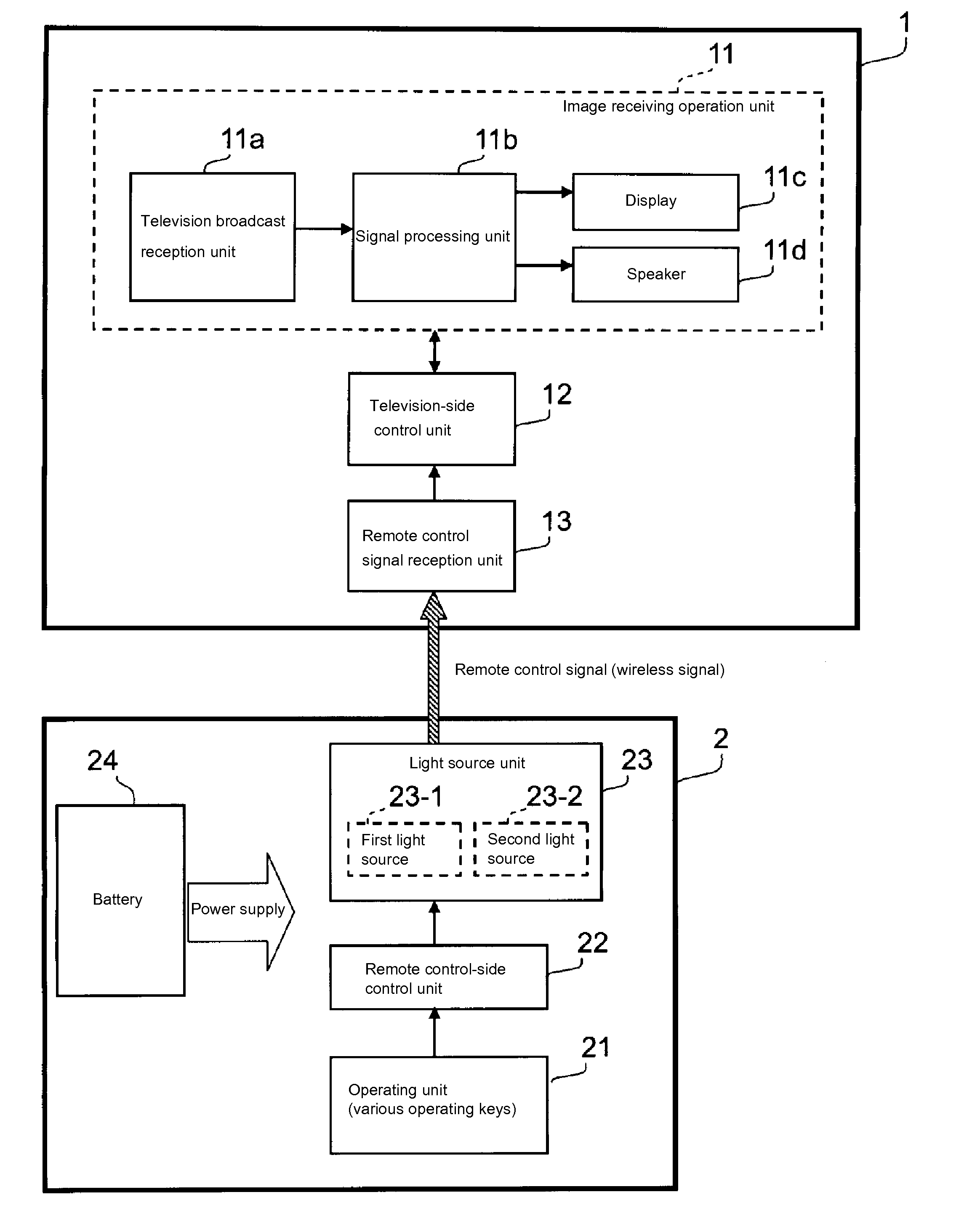
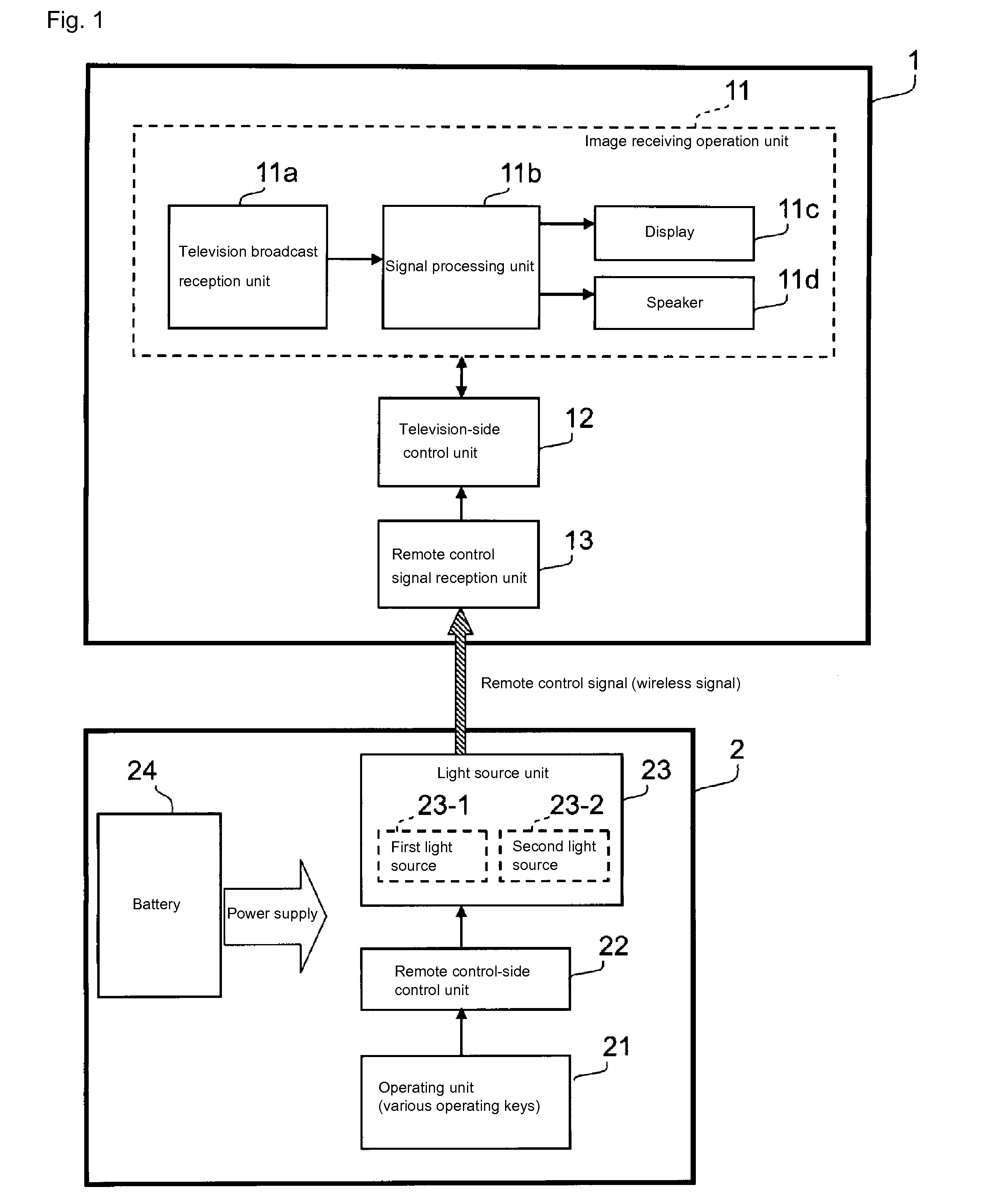
[0033]First, a first preferred embodiment of the present invention will be described. FIG. 1 is a block diagram pertaining to the configuration of the electronic equipment system according to the present preferred embodiment. This electronic equipment system, as shown in this figure, preferably includes a television broadcast receiver 1 and a remote control device 2, for example.
[0034]The television broadcast receiver 1 includes an image receiving operation unit 11, a television-side control unit 12, and a remote control signal reception unit 13. Furthermore, the image receiving operation unit 11 includes a television broadcast reception unit 11a, a signal processing unit 11b, a display 11c, a speaker 11d, and the like.
[0035]The television broadcast reception unit 11a is connected to an antenna, for example, and receives broadcast signals of television broadcasts as input. These broadcast signals contain the information on images and audio of television programs. Moreover, the telev...
second preferred embodiment
[0079]Next, a second preferred embodiment of the present invention will be described. Note that the second preferred embodiment preferably is basically the same as the first preferred embodiment, except for the points pertaining to the operating mode switch processing. In the following description, emphasis is placed on the description of the areas that are different from the first preferred embodiment, and the description of shared areas may be omitted.
[0080]The details of the operating mode switch processing in the second preferred embodiment will be described below with reference to the flowchart shown in FIG. 5. Note that the operating mode switch processing in the second preferred embodiment is different from the case of the first preferred embodiment mainly in that processes in steps S11 and S12 are added.
[0081]When any one of the operating keys is pressed (Y in step S1) in the normal mode, the remote control-side control unit 22 recognizes whether or not this pressed operatin...
third preferred embodiment
[0089]Next, a third preferred embodiment of the present invention will be described. In the following description, emphasis is placed on the description of the areas that are different from the first preferred embodiment, and the description of shared areas may be omitted.
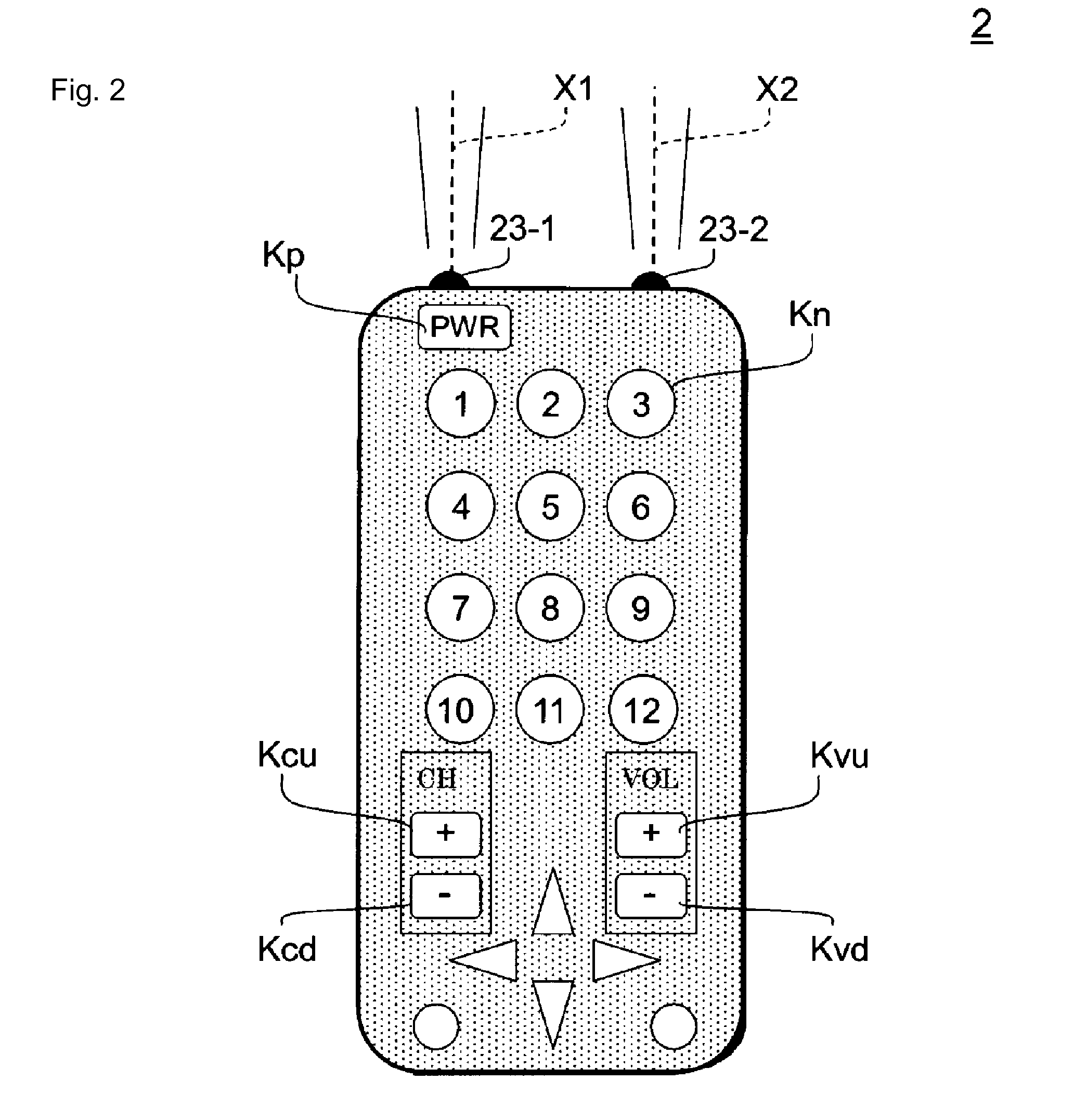
[0090]FIG. 6 is a block diagram pertaining to the configuration of the electronic equipment system according to the third preferred embodiment. In addition, FIG. 7 is an external appearance diagram of the remote control device 2 according to the third preferred embodiment. This electronic equipment system as shown in FIG. 6 includes a television broadcast receiver 1 and a remote control device 2 and is similar to the first preferred embodiment in this respect. However, the light source unit 23 of the remote control device 2 in the third preferred embodiment preferably includes a single light source 23a instead of including a first light source 23-1 and a second light source 23-2. The light source 23a is a light sou...
PUM
 Abstract
Description
Claims
Application Information