
Power regulating circuit and liquid crystal display device

a technology of power regulating circuit and which is applied in the field of display, can solve the problems of increasing the energy consumption of the liquid crystal display device, reducing and increasing the power consumption of the light emitting uni

Active Publication Date: 2018-02-20
TCL CHINA STAR OPTOELECTRONICS TECH CO LTD
View PDF5 Cites 0 Cited by
  • Summary
  • Abstract
  • Description
  • Claims
  • Application Information

AI Technical Summary

Benefits of technology

The present invention is a power regulating circuit for a light emitting unit. It includes a control chip and a voltage regulating unit. The control chip receives a brightness signal and a power consumption signal, and sends a first control signal and a second control signal based on these signals. The voltage regulating unit includes a voltage amplitude adjusting unit and a voltage duty ratio adjusting unit. The voltage amplitude adjusting unit reduces the amplitude of the first supply voltage based on the first control signal, while the voltage duty ratio adjusting unit increases the duty ratio of the first supply voltage based on the second control signal. This results in a reduction in power consumption of the light emitting unit without affecting its brightness. The power regulating circuit is efficient and effective in reducing energy consumption.

Problems solved by technology

However, in prior art, even the light emitting brightness of the light emitting unit is adjusted to be the disclosed brightness, the power consumption of the light emitting unit remains to be larger.
Thus, it makes the energy consumption of the liquid crystal display device higher.

Method used


Image

  • Power regulating circuit and liquid crystal display device
  • Power regulating circuit and liquid crystal display device
  • Power regulating circuit and liquid crystal display device

Examples


Embodiment Construction

[0020]Embodiments of the present invention are described in detail with the technical matters, structural features, achieved objects, and effects with reference to the accompanying drawings as follows. It is clear that the described embodiments are part of embodiments of the present invention, but not all embodiments. Based on the embodiments of the present invention, all other embodiments to those of ordinary skill in the premise of no creative efforts obtained, should be considered within the scope of protection of the present invention.

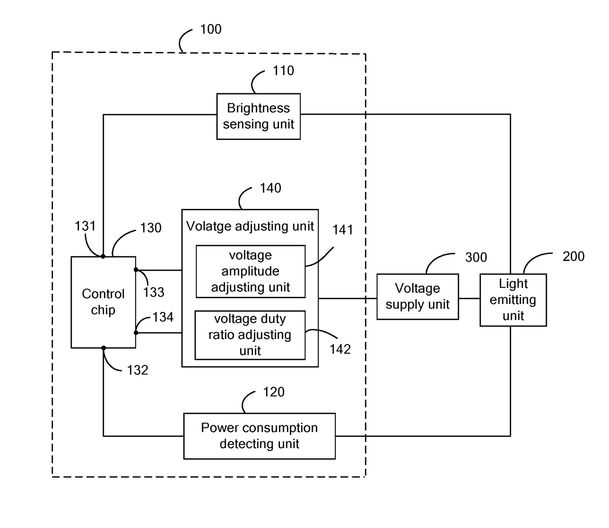
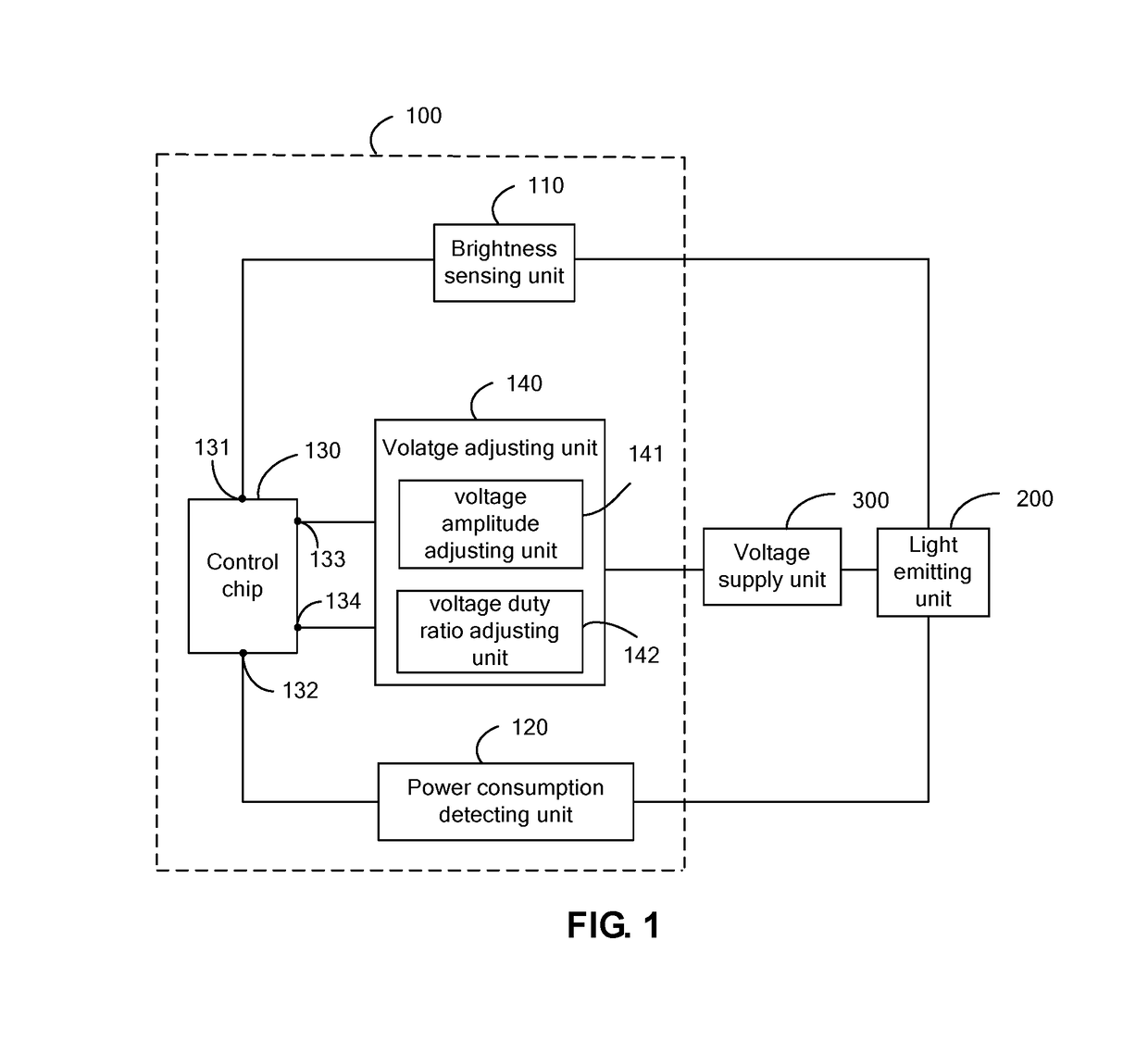
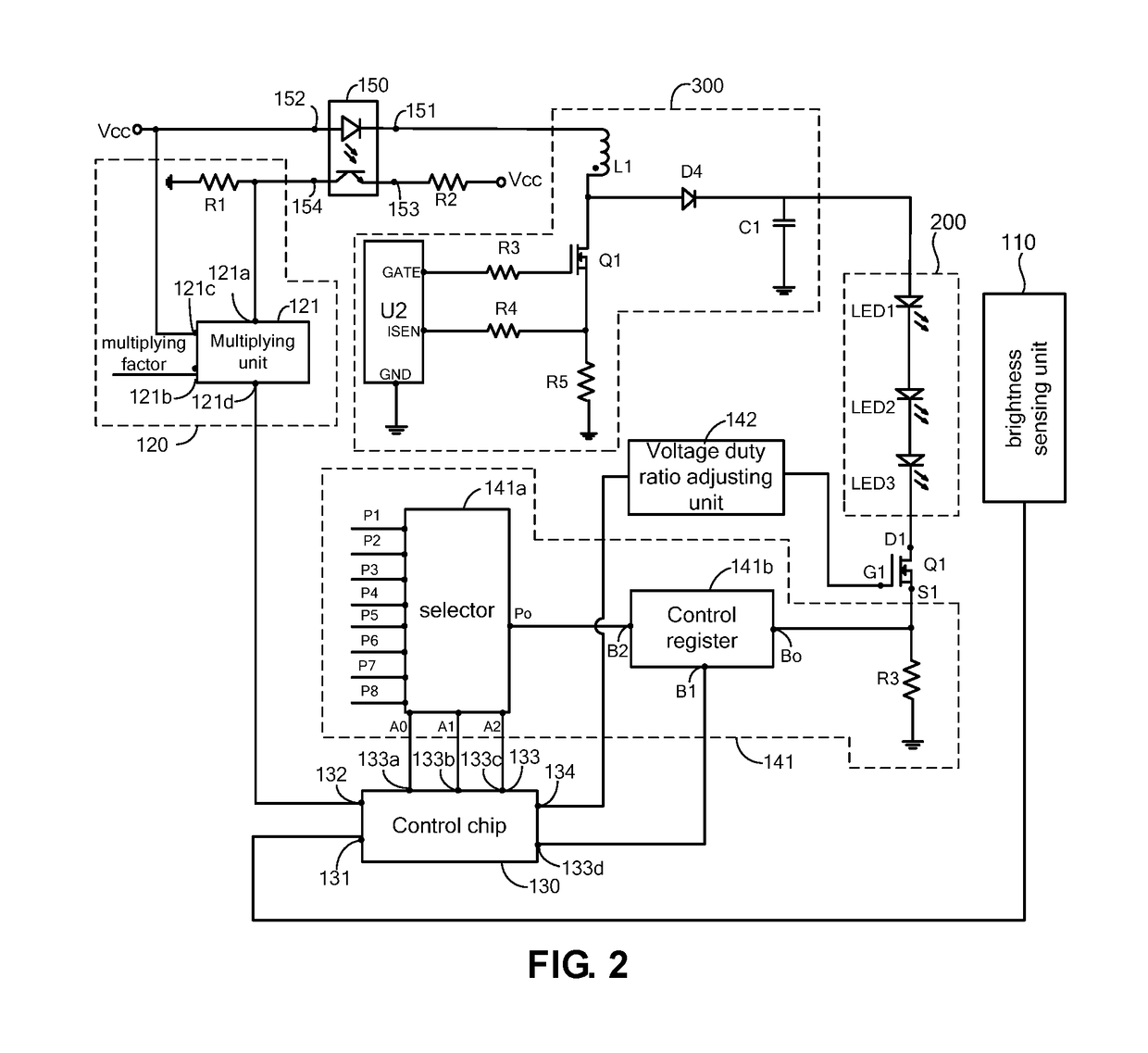
[0021]Please refer to FIG. 1 and FIG. 2. FIG. 1 is a circuit structure diagram of a power regulating circuit according to one preferred embodiment of the present invention; FIG. 2 is a specific circuit diagram of a power circuit according to one preferred embodiment of the present invention. The power regulating circuit 100 is employed to adjust a power consumption of a light emitting unit 200. The light emitting unit 200 is applied with a first su...


PUM


Abstract

The present invention provides a power regulating circuit and a liquid crystal display device. The light emitting unit is applied with a first supply voltage for emitting light, and the power regulating circuit comprises a brightness sensing unit, a power consumption detecting unit, a control chip and a voltage regulating unit, and the brightness sensing unit senses a brightness, and the power consumption detecting unit detects a power consumption, which is a first power consumption, and the control chip compares the first power consumption with a minimum power consumption of a current brightness of the light emitting unit, and as a difference of the first power consumption and the minimum power consumption is larger than a preset threshold value, the control chip controls the voltage regulating unit to decrease an amplitude of the first supply voltage and to increase a duty ratio of the first supply voltage.

Description

CROSS REFERENCE[0001]This application claims the priority of Chinese Patent Application No. 201610028074.5, entitled “Power regulating circuit and liquid crystal display device”, filed on Jan. 15, 2016, the disclosure of which is incorporated herein by reference in its entirety.FIELD OF THE INVENTION[0002]The present invention relates to a display field, and more particularly to a power regulating circuit and a liquid crystal display device.BACKGROUND OF THE INVENTION[0003]With the development of the display technology, the liquid crystal display panel possesses properties of small volume and light weight, low power consumption. Therefore, it has been favored by the users. The liquid crystal display device generally comprises the backlight module and the liquid crystal display panel. The backlight module is employed to provide the light for the liquid crystal display panel, and the liquid crystal display panel is employed to show information of words and images. The backlight module...

Claims


Application Information

Patent Timeline
Patent Type & Authority Patents(United States)
IPC IPC(8): H05B33/08G09G3/34H05B44/00
CPCH05B33/0815H05B33/0851G09G3/3406G09G3/3413G09G2320/0633G09G2320/064G09G2330/023G09G2360/145H05B45/3725H05B45/12
Inventor CAO, DAN
Owner TCL CHINA STAR OPTOELECTRONICS TECH CO LTD
Learn More