Drive apparatus and electric power steering apparatus using the same
a technology of electric power steering and drive apparatus, which is applied in the direction of electrical steering, electronic commutators, transportation and packaging, etc., can solve the problem that the same information cannot be transmitted to the plurality of substrates, and achieve the effect of minimizing the increase of the wiring spa
- Summary
- Abstract
- Description
- Claims
- Application Information
AI Technical Summary
Benefits of technology
Problems solved by technology
Method used
Image
Examples
first embodiment
[0037]With reference to FIGS. 1 to 8, the first embodiment of the present disclosure will be described.
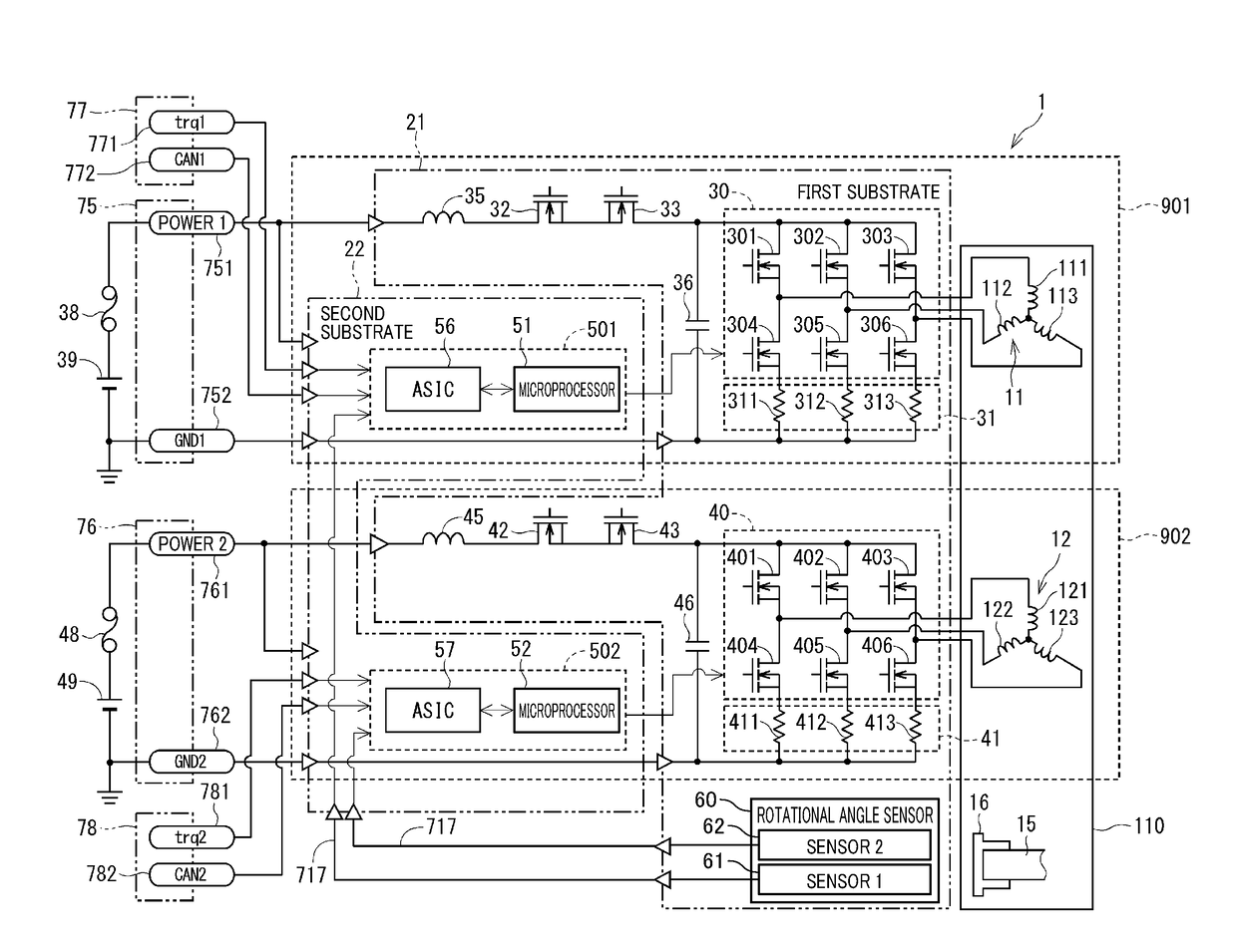
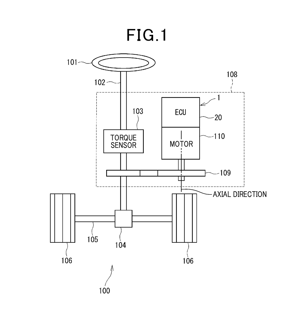
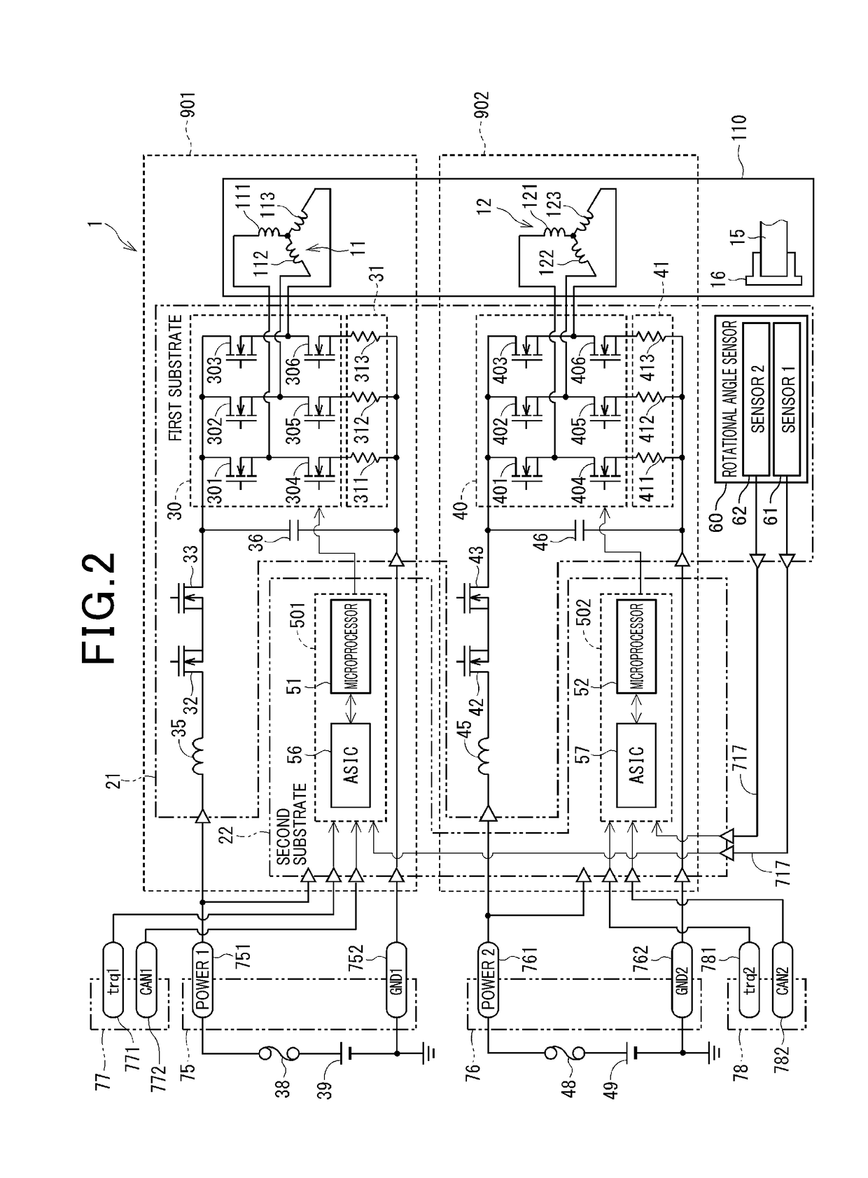
[0038]As shown in FIG. 1, the drive apparatus 1 is applied to an electric power steering apparatus 108 that assists a steering operation by the driver. A motor 110 as a rotary electric machine and a controller 20 that performs a driving control of the motor 110 are integrated to configure the drive apparatus 1. In FIG. 1, the controller 20 is indicated as “ECU”.
[0039]FIG. 1 illustrates an overall configuration of a steering system 100 provided with an electric power steering apparatus 108. The steering system 100 is configured of a steering wheel 101 as a steering member, a column shaft 102, a pinion gear 104, a rack shaft 105, a wheel 106, and an electric power steering apparatus 108 or the like.
[0040]The steering wheel 101 is connected to the column shaft 102. The column shaft 102 is provided with a torque sensor 103 that detects a steering torque. A pinion gear 104 is provided a...
second embodiment
[0142]With reference to FIG. 9, the second embodiment of the present disclosure will be described.
[0143]The drive apparatus according to the second embodiment differs from the above-described embodiment in that the second signal connector 78 is omitted and one signal connector 77 is provided. The signal transmitted through the signal connector 77 is used for the first control unit 501 and the second control unit 502. According to the second embodiment, similar to the above-described embodiment, the power terminals751 and 761, and the ground terminals 752 and 762 of the power supply connectors 75 and 76, and the internal signal terminal 717 correspond to the connection terminals. The connection between respective terminals and the first substrate 21 and the second substrate 22 is also similar to the above-described embodiment. According to this configuration, similar effects to the above-described embodiment can be obtained.
third embodiment
[0144]With reference to FIGS. 10 and 11, the third embodiment of the present disclosure will be described. FIG. 11 is a cross-sectional view corresponding to FIG. 4 of the first embodiment. Also, FIGS. 14, 16 and 21 which will be described later are similar. The drive apparatus 3 of the present embodiment is similar to the second embodiment, in which the second signal connector 78 is omitted and single signal connector 77 is provided.
[0145]In the drive apparatus 3 according to the third embodiment, similar to the second embodiment, the second signal connector 78 is omitted, and single signal connector 77 is provided.
[0146]Moreover, according to the third embodiment, the first power supply connector 75 is connected to the first substrate 21 and not connected to the second substrate 22. The second power supply connector 76 is connected to the second substrate 22 and not connected to the first substrate 21. According to the third embodiment, the power connectors 75 and 76 are provided ...
PUM
 Abstract
Description
Claims
Application Information
 - R&D
- Intellectual Property
- Life Sciences
- Materials
- Tech Scout
- Unparalleled Data Quality
- Higher Quality Content
- 60% Fewer Hallucinations
Browse by: Latest US Patents, China's latest patents, Technical Efficacy Thesaurus, Application Domain, Technology Topic, Popular Technical Reports.
© 2025 PatSnap. All rights reserved.Legal|Privacy policy|Modern Slavery Act Transparency Statement|Sitemap|About US| Contact US: help@patsnap.com


