Exhaust gas purification catalyst
a purification catalyst and exhaust gas technology, applied in metal/metal-oxide/metal-hydroxide catalysts, physical/chemical process catalysts, separation processes, etc., can solve the problems of insufficient catalyst use, low purification performance of catalyst metal, and ineffective utilization of catalyst metal, so as to reduce the amount of use, enhance the warm-up property of catalyst metal, and the effect of warming up tim
Active Publication Date: 2017-10-19
CATALER CORP
View PDF8 Cites 4 Cited by
- Summary
- Abstract
- Description
- Claims
- Application Information
AI Technical Summary
Benefits of technology
[0017]In another preferred aspect of the exhaust gas purification catalyst disclosed herein, the high density section is formed over a surface area of 9% to 64% with respect to 100% as the total surface area of a cross-section perpendicular to the direction of exhaust gas flow. As a result it becomes possible to bring out the effect of the present invention (i.e. reducing the use amount or enhancing the warm-up property of the catalyst metal) to a yet higher level.
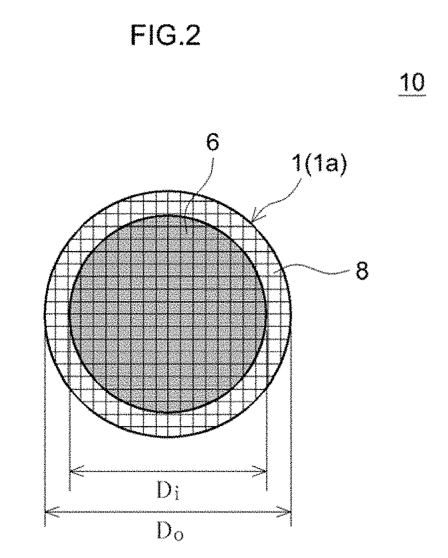
[0018]In another preferred aspect of the exhaust gas purification catalyst disclosed herein, the leading end section of the exhaust gas purification catalyst is a circle, and has the portion where the exhaust gas flow rate is relatively high, in an inner circumference part including the center of the circle, and the portion where the exhaust gas flow rate is relatively low in an outer peripheral portion adjacent to the inner circumference part. In the leading end section, preferably, the high density section is formed in the inner circumference part, the diameter of which is set to the inner diameter of the substrate, which is 30% to 80% of the outer diameter.
[0019]In another preferred aspect of the exhaust gas purification catalyst disclosed herein, the high density section is formed at a position spaced from t
Problems solved by technology
During warm-up, moreover, the exhaust gas purification catalyst is not sufficiently heated, and the purification performance of the catalyst metal tends to be low (See Patent Literature 2 and 3).
As a resu
Method used
View moreImage
Smart ImageViewing Examples

Examples
 PUM
| Property | Measurement | Unit |
|---|---|---|
| Fraction | aaaaa | aaaaa |
| Fraction | aaaaa | aaaaa |
| Fraction | aaaaa | aaaaa |
Abstract
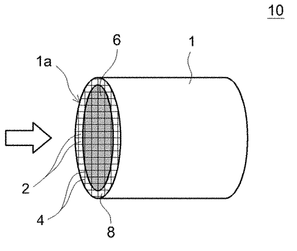
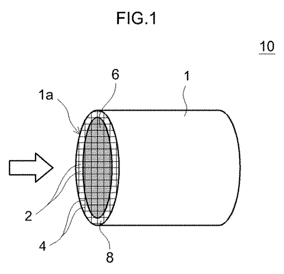
Provided is an exhaust gas purification catalyst in which the performance of a catalyst metal can be brought out properly, the purification catalyst boasting excellent purification performance during warm-up of an internal combustion engine. The exhaust gas purification catalyst 10 is provided with a substrate 1 and a catalyst layer. A leading end section 1a positioned upstream in the direction of exhaust gas flow (arrow) has a portion in which the flow rate of exhaust gas is relatively high and a portion in which the flow rate of exhaust gas is relatively low during warm-up of the internal combustion engine. The catalyst, layer in the portion of relatively high flow rate of exhaust gas has a high density section 6 in which a noble metal, is supported at relatively high density. The high density section 6 is formed to be shorter than the total length of the exhaust gas purification catalyst 10 from the leading end section 1a in the direction of exhaust gas flow.
Description
TECHNICAL FIELD[0001]The present invention relates to an exhaust gas purification catalyst that is provided in the exhaust system of an internal combustion engine. More particularly, the present invention relates to an exhaust gas purification catalyst in which a catalyst metal is supported, at high density, in specific portions of a catalyst layer.[0002]The present international patent application claims priority based on Japanese Patent Application No. 2014-184125, filed on Sep. 10, 2014, the entire contents whereof are incorporated in the present description by reference.BACKGROUND ART[0003]Harmful components such as hydrocarbons (HC), carbon monoxide (CO) and nitrogen oxides (NOx) are present in exhaust gas that is emitted by internal combustion engines such as an automobile engine. Exhaust gas purification catalysts are conventionally used in order to remove efficiently such exhaust gas components. Exhaust gas purification catalysts adopt typically a form in which a noble racia...
Claims
Login to View More Application Information
Patent Timeline
 IPC IPC(8): B01J23/46B01D53/94B01J37/02B01J37/04B01J35/00B01J23/44B01J23/10B01J21/04F01N3/28B01J35/04
CPCB01J23/464B01D2255/9022B01J23/44B01J21/04B01J23/10B01J35/0006B01J35/0073B01J35/04B01J37/04B01J37/0244B01J37/0236F01N3/28B01D2255/1023B01D2255/407B01D2255/2092B01D53/94B01J23/63B01D53/9454F01N3/101B01D2255/1025F01N2330/60F01N2370/02F01N2510/06F01N2510/0682F01N2510/0684F01N2510/068Y02T10/12
Inventor ONOE, RYOTASAKAGAMI, SHINGOITO, TSUYOSHIMORISHITA, YUTA
Owner CATALER CORP
Features
- R&D
- Intellectual Property
- Life Sciences
- Materials
- Tech Scout
- Unparalleled Data Quality
- Higher Quality Content
- 60% Fewer Hallucinations
Learn More Browse by: Latest US Patents, China's latest patents, Technical Efficacy Thesaurus, Application Domain, Technology Topic, Popular Technical Reports.
© 2025 PatSnap. All rights reserved.Legal|Privacy policy|Modern Slavery Act Transparency Statement|Sitemap|About US| Contact US: help@patsnap.com