
Multi-stage drilling waste material recovery process

a waste material recovery and multi-stage technology, applied in drying, lighting and heating equipment, sediment separation by centrifugal force, etc., can solve problems such as contamination of residual drilling mud, and achieve the effect of improving liquid and solid recovery

Active Publication Date: 2017-10-19
RECOVERY ENERGY SERVICES INC
View PDF1 Cites 10 Cited by
  • Summary
  • Abstract
  • Description
  • Claims
  • Application Information

AI Technical Summary

Benefits of technology

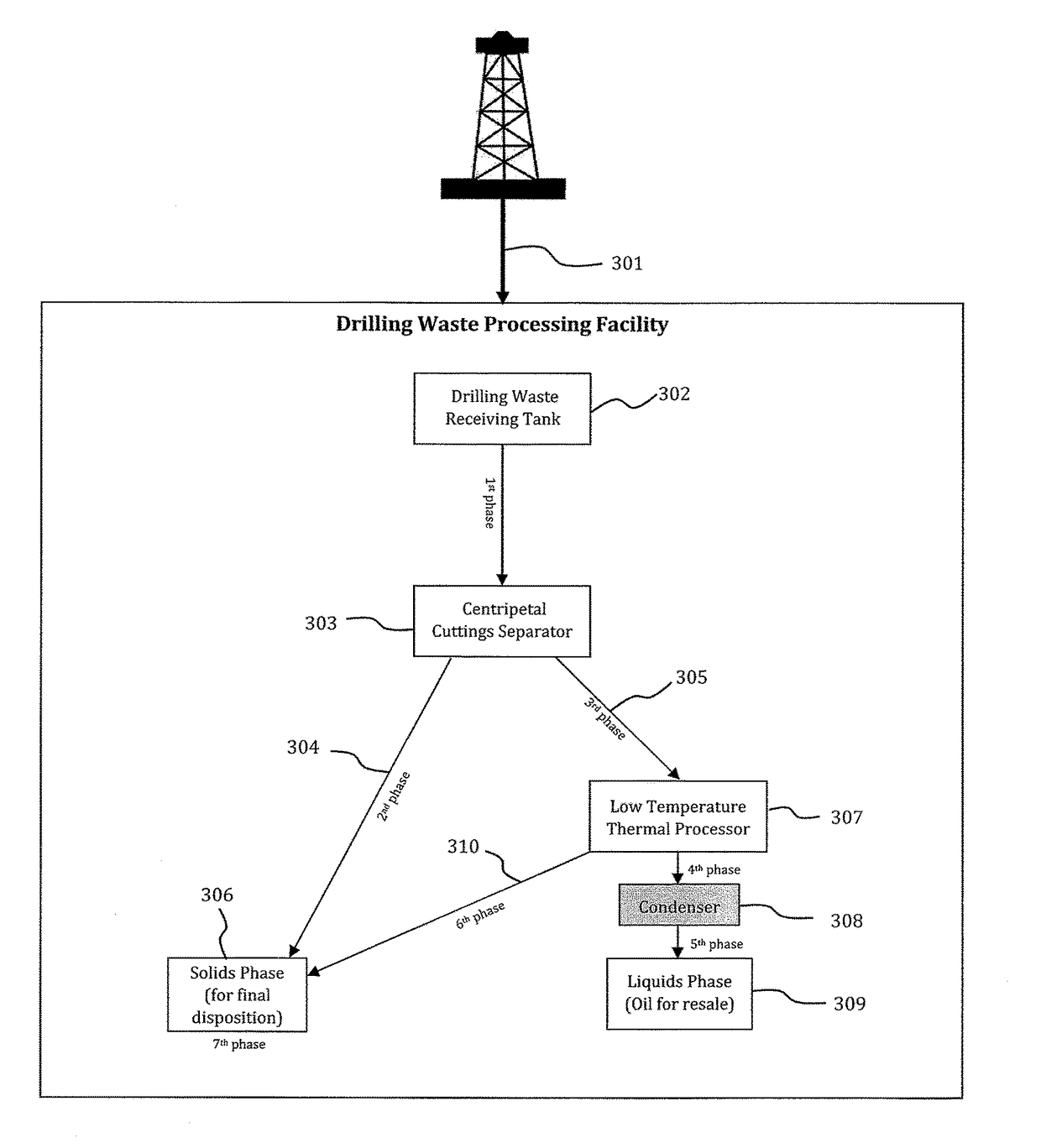
The patent describes a process for removing hydrocarbons and water from oil base mud contaminated drill cuttings and recovering liquids in a multi-stage separation process. The process involves heating the drill cuttings, separating them into a liquids phase and a solids phase, and then using a low temperature thermal process to evaporate the liquids and create a separate vapor phase. The process can increase the throughput of the low temperature thermal process and result in cleaner solids with reduced hydrocarbon contamination. The technical effects of the process include improved liquids and solids recovery, increased drill cuttings waste throughput, and cleaner solids with reduced hydrocarbon contamination.

Problems solved by technology

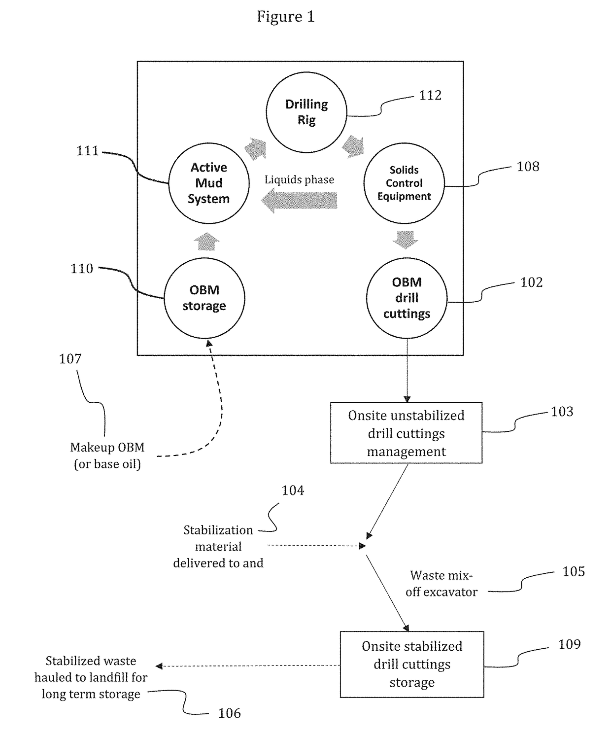
The drill cuttings still contain residual amounts of the drilling mud that couldn't be separated through mechanical means, and this residual drilling mud is considered to be contamination.

Method used


Image

  • Multi-stage drilling waste material recovery process
  • Multi-stage drilling waste material recovery process
  • Multi-stage drilling waste material recovery process

Examples


Embodiment Construction

[0021]The particulars shown herein are by way of example and for purposes of illustrative discussion of the various embodiments of the present invention only and are presented in the cause of providing what is believed to be the most useful and readily understood description of the principles and conceptual aspects of the invention. In this regard, no attempt is made to show details of the invention in more detail than is necessary for a fundamental understanding of the invention, the description making apparent to those skilled in the art how the several forms of the invention may be embodied in practice.

[0022]The present invention will now be described by reference to more detailed embodiments. This invention may, however, be embodied in different forms and should not be construed as limited to the embodiments set forth herein. Rather, these embodiments are provided so that this disclosure will be thorough and complete, and will fully convey the scope of the invention to those ski...


PUM

PropertyMeasurementUnit
temperatureaaaaaaaaaa
flash pointaaaaaaaaaa
viscosityaaaaaaaaaa

Abstract

A process for removing free liquids from oil base mud contaminated drill cuttings waste. A process is described wherein a high gravity centripetal separator and low temperature thermal process are cooperatively used to enhance the mechanical and thermal separation methods, resulting in improved efficiency of the hydrocarbon and water removal process. A process is also described wherein the oil base mud contaminated drill cuttings waste is heated to strip volatile constituents and excess water from the oil base mud contaminated drill cuttings to further enhance the mechanical and thermal separation methods resulting in improved efficiency of the hydrocarbon and water removal process. A less expensive process is also described where the oil base mud contaminated drill cuttings waste is heated to strip volatile constituents and excess water from the oil base mud contaminated drill cuttings to further enhance the recoverable liquids phase during mechanical separation. A conventional stripping process for oil base mud is also utilized.

Description

CROSS-REFERENCE TO RELATED APPLICATIONS[0001]This application claims the benefit under 35 U.S.C. §119(e) of U.S. Provisional Application Ser. No. 62 / 324,622 filed Apr. 19, 2016, the disclosure of which is expressly incorporated by reference herein in its entirety.TECHNICAL FIELD[0002]The field of art to which this invention generally pertains is the processing of drill cuttings waste.BACKGROUND[0003]During the drilling of a well, gas or oil for example, drilling mud is typically pumped down the drill string through a drill bit. The drilling mud simultaneously cools the bit and carries drill cuttings up the well bore. Drilling mud is typically comprised of a fluid (or fluids), and mixture of additives which can be either fluids or solids, forming a useable drilling fluid. Oil based or brine based drilling fluids are often used to drill oil and gas wells because they have special characteristics that make them a better cooling / carrying fluid than other drilling muds. Additionally, suc...

Claims


Application Information

Patent Timeline
Patent Type & Authority Applications(United States)
IPC IPC(8): E21B21/06B01D3/00B01D21/26F26B5/08F26B3/18
CPCE21B21/066B01D21/26E21B21/065F26B5/08F26B3/18B01D3/00B01D21/262B04B5/10
Inventor ROSS, STANSUDLOW, PAUL
Owner RECOVERY ENERGY SERVICES INC
Learn More