Supercharge Your Innovation With Domain-Expert AI Agents!

Low capacity latency storage enclosure with logic device

a logic device and low-latency technology, applied in the direction of input/output to record carriers, instruments, computing, etc., can solve the problems of limiting the number of hard drives, degrading the quality of signals transmitted via traces, and affecting the performance of the interface unit, so as to achieve the effect of reducing crosstalk

Active Publication Date: 2017-10-19
SUPER MICRO COMP
View PDF7 Cites 0 Cited by
  • Summary
  • Abstract
  • Description
  • Claims
  • Application Information

AI Technical Summary

Benefits of technology

The disclosed approach in the patent text allows for a storage enclosure that can carry more hard drives than previous methods. This is achieved by using dual-pass cables that are shielded, which reduces interference between them compared to previous methods that used PCB traces. Overall, this makes it possible to create a more efficient and reliable storage solution.

Problems solved by technology

One drawback of the configuration described above is that the routing circuitry within the interface unit includes a rather complex arrangement of traces that tends to induce crosstalk.
The crosstalk not only can degrade the quality of the signals transmitted via the traces, the crosstalk also limits the number of hard drives that can be included in the storage enclosure, because the crosstalk increases as the number of hard drives included in the storage enclosure increases.
Another drawback of the convention storage enclosure configuration described above is that the PCB traces within the single large PCB also induce crosstalk, which further limits the number of drives that can be included within the storage enclosure.
Further, if the traces within the large PCB exceed a certain length, then the quality of the signals transmitted via those traces can significantly degrade.
This constraint limits the size of the PCB, and, in turn, the number of hard drives that the PCB can support.
Yet another drawback of the above configuration is that the complex routing scheme implemented to properly couple all of the hard drives to the interface unit via the PCB traces creates timing differences in signals that are transmitted to different hard drives.
These timing differences can make synchronization between hard drives difficult or impossible.

Method used


Image

  • Low capacity latency storage enclosure with logic device
  • Low capacity latency storage enclosure with logic device
  • Low capacity latency storage enclosure with logic device

Examples


Embodiment Construction

[0019]In the following description, numerous specific details are set forth to provide a more thorough understanding of the present invention. However, it will be apparent to one of skill in the art that the present invention may be practiced without one or more of these specific details.

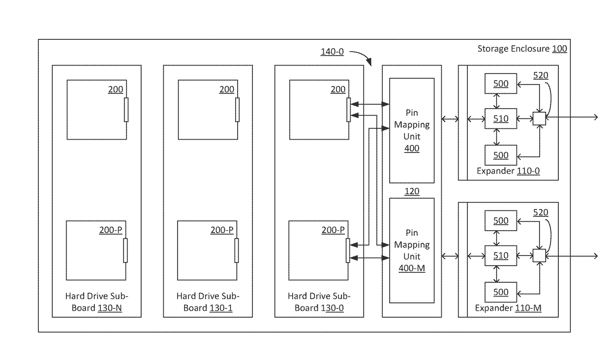
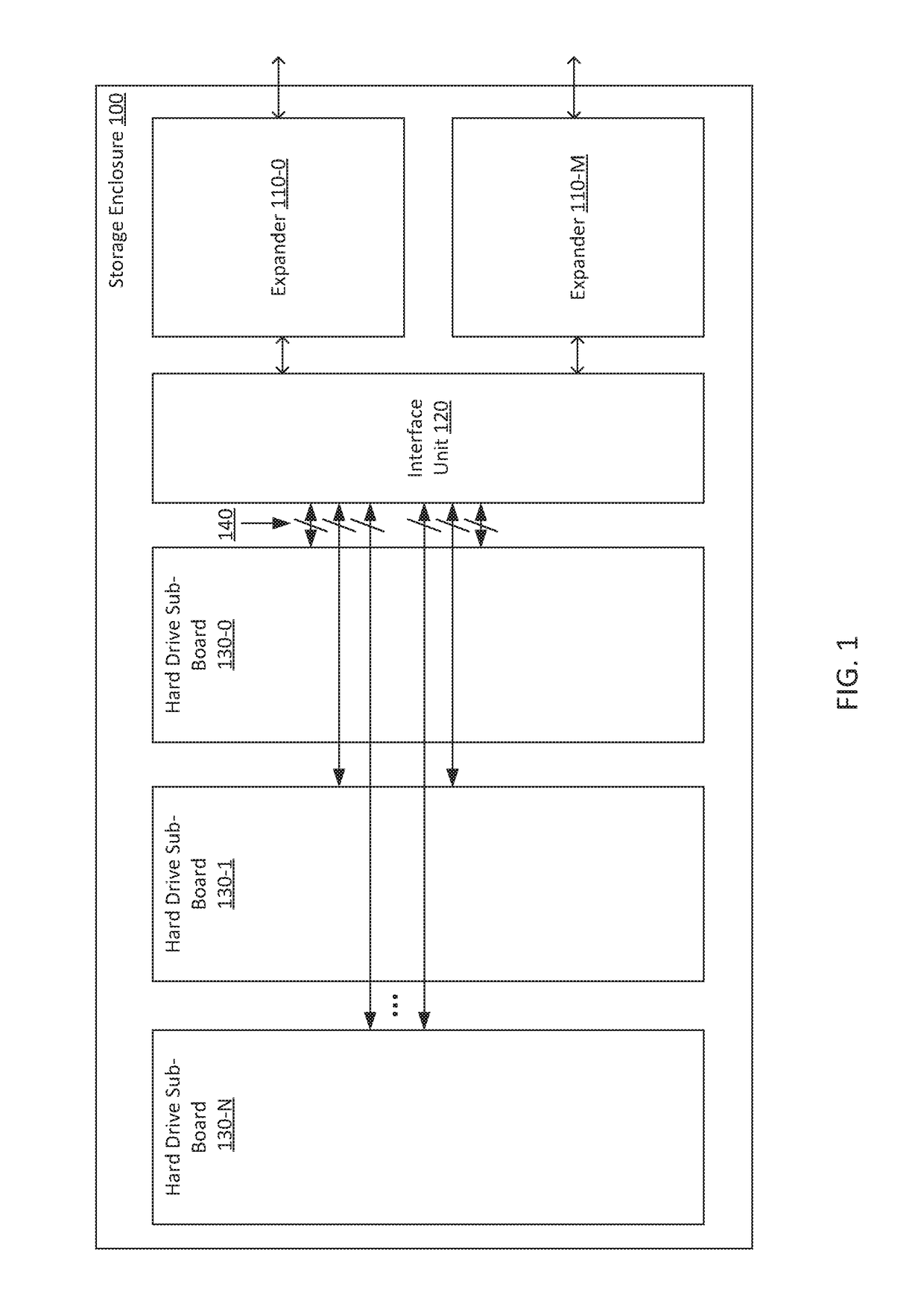
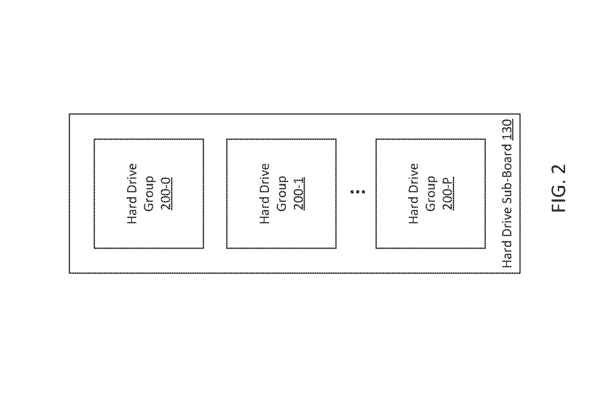
[0020]FIG. 1 is a block diagram of a storage enclosure, according to various embodiments of the present invention. As shown, storage enclosure 100 includes a plurality of expanders 110-0 through 110-M, an interface unit 120, and a plurality of hard drive sub-boards 130-0 through 130-N, each configured to include a plurality of hard drives (not shown here). Expanders 110 are coupled to interface unit 120, and interface unit 120 is coupled to hard drive sub-boards 130. Expanders 110 include a plurality of plugs (not shown) which couple directly to interface unit 120. Interface unit 120 is coupled to each hard drive sub-board 130 via a set of cables 140. Cables 140 may include multiple different subset...


PUM


Abstract

A storage enclosure includes a plurality of hard drive sub-boards, each configured to include a plurality of hard drives. Each hard drive sub-board is coupled to one or more expanders, via and interface unit, with a set of dual-pass shielded cables. The expander includes a plurality of chipsets coupled to a complex logic device. Each chipset may communicate with a different subset of hard drives with potentially different timing characteristics. The dual-pass shielded cables may be arranged to mitigate these differences. In addition, pin assignments associated with the cables may be set in order to further mitigate the timing differences.

Description

BACKGROUND OF THE INVENTIONField of the Invention[0001]Embodiments of the present invention relate generally to storage enclosures, and, more specifically, to low latency storage enclosure with large capacity.Description of the Related Art[0002]A conventional storage enclosure includes an expander coupled to an interface unit that, in turn, is coupled to a single large printed circuit board (PCB). The single large PCB includes a collection of ports for mounting hard drives. The PCB includes a set of traces that couple the hard drives to the interface unit and, in turn, to the expander. The expander may be coupled to a host computer system and receive input / output (I / O) commands from that host computer. The expander transmits these commands to the interface unit. The interface unit includes routing circuitry that routes I / O commands from the expander to specific PCB traces, thereby providing access to individual hard drives.[0003]One drawback of the configuration described above is t...

Claims


Application Information

Patent Timeline
Patent Type & Authority Applications(United States)
IPC IPC(8): G06F3/06G06F13/16G06F13/40G06F13/20
CPCG06F3/0611G06F13/20G06F3/0689G06F13/4068G06F3/0629G06F13/16G06F3/0607G06F3/0626G06F3/0655G06F3/0676
Inventor TSENG, KELVINSHIH, TRINALIANG, LAWRENCE H.CHEN, RICHARD
Owner SUPER MICRO COMP
Features
  • R&D
  • Intellectual Property
  • Life Sciences
  • Materials
  • Tech Scout
  • Unparalleled Data Quality
  • Higher Quality Content
  • 60% Fewer Hallucinations
Learn More