
Gateway-Based Anti-Theft Security System and Method

a security system and gateway technology, applied in anti-theft devices, instruments, electric programme control, etc., can solve problems such as failure to operate, alarm trigger, security system disabled,

Active Publication Date: 2017-10-19
MOBILE TECH
View PDF7 Cites 10 Cited by
  • Summary
  • Abstract
  • Description
  • Claims
  • Application Information

AI Technical Summary

Benefits of technology

The patent describes a problem with conventional security fobs in retail stores. These fobs can be easily obtained and used by anyone, which can lead to unauthorized access. To solve this issue, the patent proposes a mechanism for controlling which security fobs are authorized to control the security states of product display assemblies. This mechanism can help prevent unauthorized use of fobs and reduce the need for frequent reprogramming efforts.

Problems solved by technology

Product display assemblies typically include security systems that will trigger alarms when actions such as an improper removal of the product from the puck assembly or an improper movement of the puck assembly occur.
When in an armed state, the security system will trigger an alarm when unauthorized actions occur.
When in a disarmed state, the security system is disabled.
However, this conventional approach to security fobs results in a practical problem that relates to the turnover in personnel at a retail store.
Given the relative frequency of changes in store personnel, this need for frequent reprogramming efforts leads to inefficiency.
Such an arrangement provides a level of failsafe operations when there is a need to control the security status of a product display assembly in situations when a wireless network or the like that links the security fobs with the computer system might be down.

Method used


Image

  • Gateway-Based Anti-Theft Security System and Method
  • Gateway-Based Anti-Theft Security System and Method
  • Gateway-Based Anti-Theft Security System and Method

Examples


Embodiment Construction

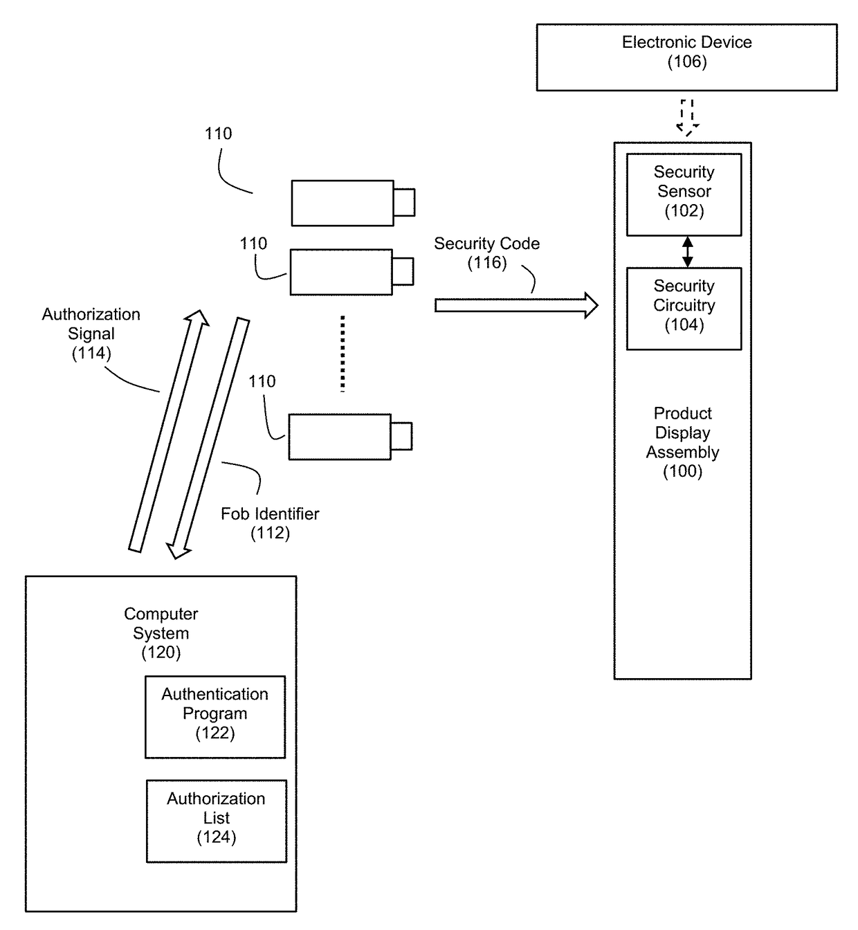
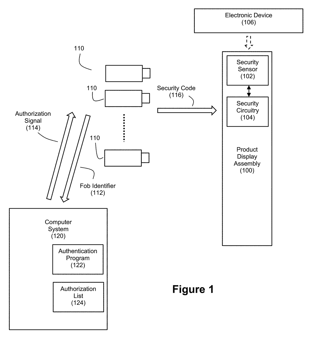
[0032]FIG. 1 discloses an example embodiment of a gateway-based authorization system for security fobs. The system can include a product display assembly 100 for cooperation with one or more security fobs 110 and a computer system 120.

[0033]The product display assembly 100 can serve as an anti-theft security system, and it can be used for presenting a product such as an electronic device 106 to consumers in a secure manner. As mentioned, examples of suitable electronic devices 106 can include hand-held consumer electronics such as smart phones, tablet computers, digital cameras, etc. The product display assembly 100 can include a security sensor 102 and security circuitry 104 that cooperate with each other to generate a security condition signal in response to detecting an event relating to a removal of the electronic device 106 from the product display assembly 100. The security circuitry 104 is controllable to be switchable between an armed state and a disarmed state based on rece...


PUM


Abstract

Improved systems and techniques are disclosed for controlling the security states of anti-theft security systems such as product display assemblies using security fobs. The tasks relating to fob authentication are offloaded to a computer system, and these authentications can be based on identifiers for the different security fobs. The interactions between security fobs and product display assemblies can be consistent regardless of the population of authorized security fobs by using a security code that is shared by the security fobs. When attempting to use a security fob to change a security status for a product display assembly, the provision of the code to the subject product display assembly can be predicated on authorization of the subject security fob by the computer system. The computer system can maintain a list of identifiers for authorized security fobs that is easily updated when new security fobs are added to or existing security fobs are de-authorized from the system.

Description

CROSS-REFERENCE AND PRIORITY CLAIM TO RELATED PATENT APPLICATIONS[0001]This patent application claims priority to U.S. provisional patent application Ser. No. 62 / 323,511, filed Apr. 15, 2016 and entitled “Alarm Key System for Retail Security Display”, the entire disclosure of which is incorporated herein by reference.[0002]This patent application also claims priority to U.S. provisional patent application Ser. No. 62 / 323,466, filed Apr. 15, 2016 and entitled “Security Alarm Key for Retail Security Display”, the entire disclosure of which is incorporated herein by reference.INTRODUCTION[0003]Many products such as electronic devices (particularly hand-held electronics such as smart phones, tablet computers, digital cameras, etc.) are displayed in retail stores at individual post positions on countertop or wall-rack displays. A product display assembly at each post position is typically employed to facilitate the presentation of these products to customers. The product display assembly...

Claims


Application Information

Patent Timeline
IPC IPC(8): G08B13/24
CPCG08B13/2434H04B1/3877G08B13/1454G08B25/008G06F21/34G06F21/45G06F21/88B60R25/1003B60R25/24G08B13/1445H04W12/0471H04W12/082H04W4/50H04W48/08H04W48/02H04W48/00G08C2201/20G08C2201/21G05B19/04H04W48/16G07C9/20F17D3/01G07C9/00174G07C9/00817G08B13/14G08B13/2431H04B1/3816H04W12/04H04W12/08G06F21/31B60R2225/00G07C2009/00769G08B13/06
Inventor BLASER, ROBERT LOGANSCHATZ, KRISTOPHER WENDELLWYLIE, HUNTER ANDERSON
Owner MOBILE TECH
Learn More