Low profile antenna system

a low-profile antenna and antenna technology, applied in the field of wireless communication, can solve the problems of antenna introduction of a trip hazard, m2m applications can be demanding, ground level, etc., and achieve the effect of reducing the height form factor

Active Publication Date: 2017-10-19
KYOCERA AVX COMPONENTS (SAN DIEGO) INC
View PDF8 Cites 9 Cited by
  • Summary
  • Abstract
  • Description
  • Claims
  • Application Information

AI Technical Summary

Benefits of technology

The patent describes an antenna system that can emit signals in all directions, while keeping its overall size small. The system can adjust its resonance frequency during production and use. Additionally, it can change its radiation pattern dynamically. This makes it suitable for applications where low-profile antennas need to transmit vertical signals without being a safety hazard.

Problems solved by technology

Some M2M applications can be demanding when a low profile antenna is required, specifically when the height allocated for the antenna is not sufficient for efficient operation at the required frequency.
If the antenna is operating at an industrial scientific and medical (ISM) frequency band such as, for example, 434 MHz or 915 MHz, the height required for efficient antenna operation when placed at ground level might be such that the antenna introduces a trip hazard.
Many of the commercial wireless applications, such as M2M and IoT applications, require an antenna to transmit or receive equally well over wide fields of view since there could be motion involved in the application or a lack of consistency in communication system architecture such that the placement of communication nodes varies from one installation to the next.
When a low profile antenna module is required, and the frequency of operation is such that the height or thickness allowed for the antenna module is a fraction of a wavelength, it is generally difficult to achieve uniform radiation pattern coverage in a plane of the antenna that is normal to the axis aligned with the dimension of reduced height.
Additionally, it is generally difficult to achieve uniform pattern coverage in the plane normal to the axis aligned with the dimension of reduced height when the polarization of the antenna is required to align with the axis normal to the dimension of reduced height.
For example, it is generally difficult to design an antenna module with vertical polarization referenced to the ground when the antenna is required to be placed on the ground, especially when uniform coverage is required in the plane of the antenna.

Method used


Image

  • Low profile antenna system
  • Low profile antenna system
  • Low profile antenna system

Examples


Embodiment Construction

[0025]For purposes of explanation and not limitation, details and descriptions of certain preferred embodiments are hereinafter provided such that one having ordinary skill in the art may be enabled to make and use the invention. These details and descriptions are representative only of certain preferred embodiments. However, a myriad of other embodiments which will not be expressly described will be readily understood by those having skill in the art upon a thorough review hereof. Accordingly, any reviewer of the instant disclosure should interpret the scope of the invention by the claims, and such scope shall not be limited by the embodiments described and illustrated herein.

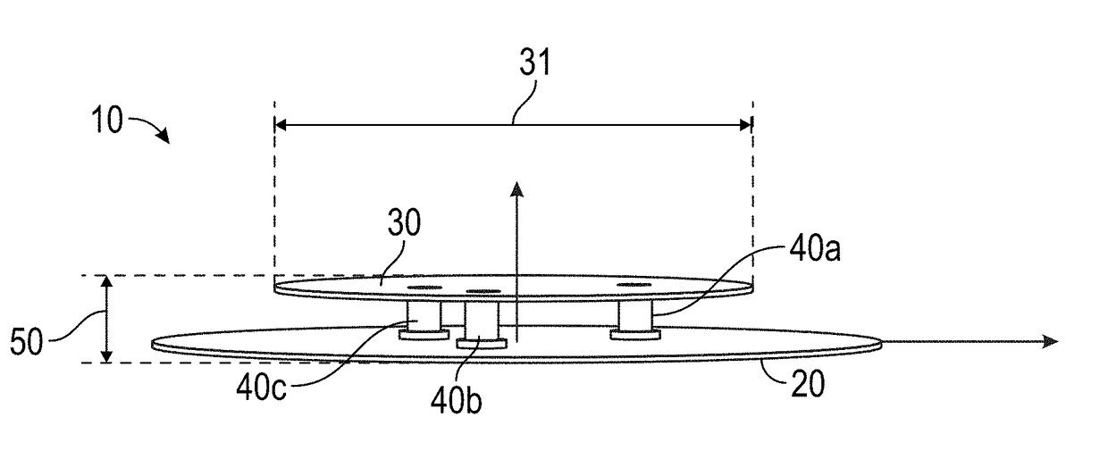
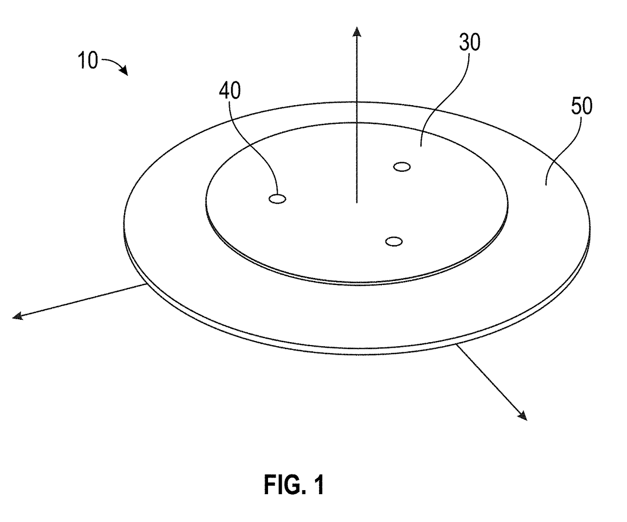
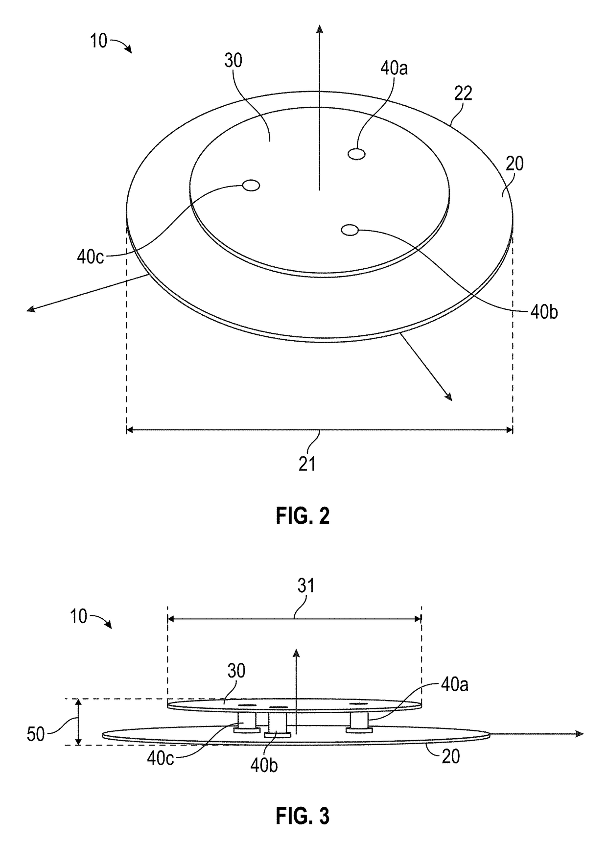
[0026]In a general embodiment, a low profile antenna system is provided. The antenna system is capable of variable tuning and good performance for applications where the antenna is installed on a walking surface.

[0027]In one embodiment of the antenna system, a radiating element is positioned above a ground pla...


PUM


Abstract

An antenna system is described where uniform radiation pattern coverage is provided in the plane of a low profile antenna element. A polarization that is orthogonal to the plane of the low profile antenna element can be achieved for the radiated field. Tuning mechanisms are described to provide a method for dynamically altering the radiation pattern and for adjusting the frequency response of the antenna during the manufacturing process as well as at field installation. The antenna system is capable of being implemented in applications such as local area network (LAN), cellular communication network, and machine to machine (M2M).

Description

CROSS-REFERENCE TO RELATED APPLICATIONS[0001]This application claims benefit of U.S. Provisional Ser. No. 62 / 324,840, filed Apr. 19, 2016, titled “LOW PROFILE ANTENNA SYSTEM”; the entire contents of which are hereby incorporated by reference.BACKGROUND OF THE INVENTIONField of the Invention[0002]This invention relates generally to the field of wireless communication. In particular, the invention relates to an antenna system configured to provide low profile attributes and tuning capabilities.Description of the Related Art[0003]A proliferation of wireless communication systems such as wireless wide area networks (WWANs) also referred to as “cellular systems”, wireless local area networks (WLANs), machine to machine (M2M) systems, and internet of things (IoT) applications, has increased the number and types of devices and infrastructure that antennas are, or will, need to be designed into and / or integrated with.[0004]Some M2M applications can be demanding when a low profile antenna is...

Claims


Application Information

Patent Timeline
Patent Type & Authority Applications(United States)
IPC IPC(8): H01Q9/04H01Q1/42H01Q9/16H01Q1/38
CPCH01Q9/0421H01Q1/38H01Q9/16H01Q9/0442H01Q1/42H01Q5/328H01Q5/378
Inventor DESCLOS, LAURENTSHAMBLIN, JEFFREY
Owner KYOCERA AVX COMPONENTS (SAN DIEGO) INC
Why Eureka
Try Eureka