Physiological monitoring system

a monitoring system and physiological technology, applied in the field of physiological monitoring technology, can solve the problems of patients being unable to call actively, inconvenient for patients, and still a lot of inconvenien

Active Publication Date: 2017-10-26
TAIWAN AULISA MEDICAL DEVICES TECH INC
View PDF2 Cites 3 Cited by
  • Summary
  • Abstract
  • Description
  • Claims
  • Application Information

AI Technical Summary

Benefits of technology

The present invention is a monitoring system that allows one or more users to wear a portable monitoring module that can capture their physiological status and image. The system includes a display module that can display the user's information. The system also has the ability to automatically pair control to avoid showing the wrong user information and can store correct data of the user before and after an abnormal situation occurs. The system can synchronize the user's physiological signals and image to prevent errors during data transmission. The technical effects of the invention include improved monitoring of user health and image, convenient and stable installations, and prevention of errors and disorders during data transmission.

Problems solved by technology

However, such arrangement is very inconvenient to the patients.
In some special situations, the patients may be unable to call actively.
Although a sensing device may be installed to obtain the condition and situation of a care receiver, yet only data are transmitted, and there are still a lot of inconveniences.
In addition, no automatic or manual pairing mechanism is established between the conventional sensing device and monitoring device connected through the Internet, and thus there is an issue of having errors or disorders in the transmission of information between the conventional sensing device and monitoring device via the Internet.

Method used


Image

  • Physiological monitoring system
  • Physiological monitoring system
  • Physiological monitoring system

Examples


Embodiment Construction

[0024]The aforementioned and other objects, characteristics and advantages of the present invention will become apparent with the detailed description of the preferred embodiments and the illustration of related drawings as follows.

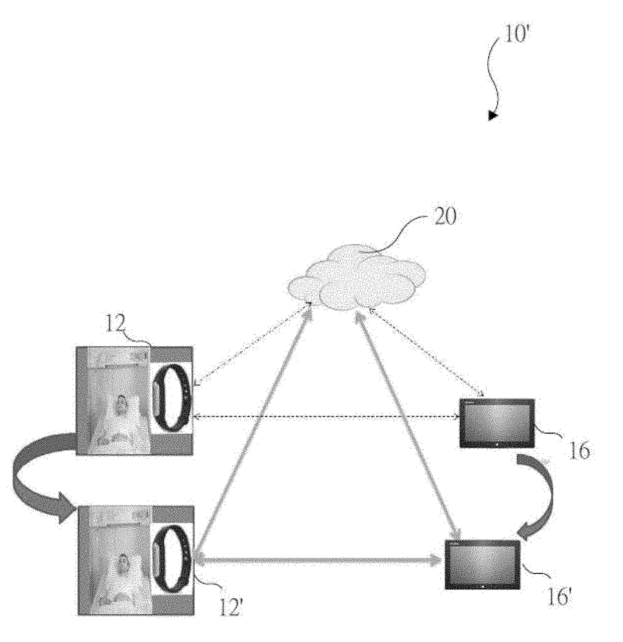
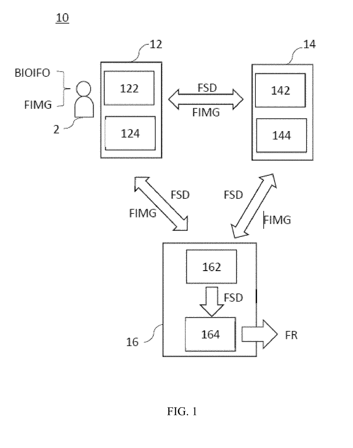
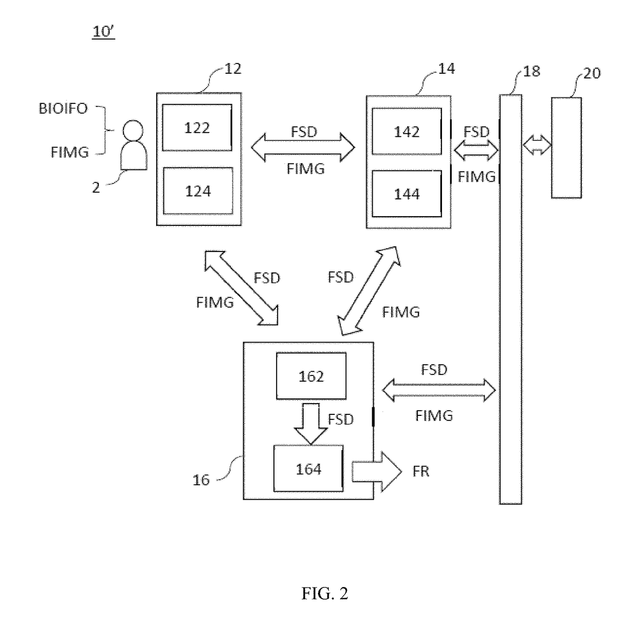
[0025]With reference to FIG. 1 for a schematic block diagram of a physiological monitoring system in accordance with the first preferred embodiment of the present invention, the physiological monitoring system 10 comprises a near-end portable monitoring module 12, an image sensing module 14 and a near-end information display module 16, and the physiological monitoring system 10 is provided for monitoring a physiological status BIOIFO or a physiological status BIOIFO and a first image FIMG.

[0026]The near-end portable monitoring module 12 further comprises a first communication unit 122 and a first sensing unit 124. The near-end portable monitoring module 12 is provided for the user 2 to wear and for sensing the physiological status BIOIFO of the user 2 to ...


PUM


Abstract

A physiological monitoring system includes a near-end portable monitoring module for generating first sensed data, capturing a user's first image, an image sensing module for synchronizing the first sensed data and the first image to form first combination data, and searching and connecting the corresponding near-end portable monitoring module to receive the first sensed data and display the near-end information display module corresponding to the screen of the first combination data, when the first sensed data includes a warning signal, the first combination data is transmitted and stored in the Internet by the second communication unit within a time period from a first time before the warning signal is issued to a second time for releasing the warning signal, and the first combination data within the time period from the first time to the second time is transmitted to the near-end information display module to display the first combination data.

Description

FIELD OF THE INVENTION[0001]The present invention relates to the field of physiological monitoring technology, in particular to a physiological monitoring system for monitoring the physiological status and / or image of a user wearing a portable monitoring module.BACKGROUND OF THE INVENTION[0002]In general, a conventional medical healthcare system allows patients to call a doctor or medical professional by an active method such as ringing an alarm bell. However, such arrangement is very inconvenient to the patients. In some special situations, the patients may be unable to call actively. The same situation may occur in a home care environment. Although a sensing device may be installed to obtain the condition and situation of a care receiver, yet only data are transmitted, and there are still a lot of inconveniences.[0003]In addition, no automatic or manual pairing mechanism is established between the conventional sensing device and monitoring device connected through the Internet, an...

Claims


Application Information

Patent Timeline
Patent Type & Authority Applications(United States)
IPC IPC(8): A61B5/00A61B5/11G08B29/18G16Z99/00
CPCA61B5/0022A61B5/0077A61B5/746A61B5/0013A61B2562/029A61B5/742G08B29/185A61B2562/0204A61B2562/0271A61B5/1128A61B7/00A61B5/01A61B5/11A61B2560/0242A61B2560/0431A61B2562/0257G16H40/63G16H40/67G16Z99/00
Inventor LIEN, AUGUSTINE YEN
Owner TAIWAN AULISA MEDICAL DEVICES TECH INC
Why Eureka
Try Eureka