Battery mounting structure for vehicle

a technology for mounting structures and batteries, applied in the direction of batteries, cell components, electric devices, etc., can solve the problems of unusual odor, rusted battery packs, etc., and achieve the effect of preventing water intrusion into the clearance between the floor panel and the battery pack, and preventing water accumulation on the top face of the battery pack

Active Publication Date: 2017-10-26
TOYOTA JIDOSHA KK
View PDF3 Cites 27 Cited by
  • Summary
  • Abstract
  • Description
  • Claims
  • Application Information

AI Technical Summary

Benefits of technology

[0013]Thus, according to the embodiment of the present application, the sealing member is interposed between the periphery of the battery pack and the portion extending from the member including the frame member opposed to the battery pack. According to the embodiment of the present application, therefore, water intrusion into a clearance between a floor panel and the battery pack may be prevented. In addition, the drain hole is formed in the sealing member to provide a connection between an inner side and an outer side of the sealing member in a width direction of the vehicle. According to the first example, therefore, water condensed on a surface of the battery pack may be drained toward the frame member. For this reason, water accumulation on the top face of the battery pack may be prevented.

Problems solved by technology

However, water may intrude into a clearance between the battery pack and the floor panel, and the intruding water may accumulate on the battery pack.
Consequently, the intruding water may give out unusual odor and the battery pack may be rusted the by the intruding water.

Method used


Image

  • Battery mounting structure for vehicle
  • Battery mounting structure for vehicle
  • Battery mounting structure for vehicle

Examples


Embodiment Construction

)

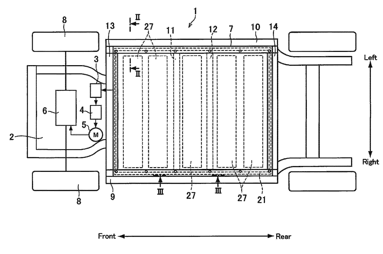
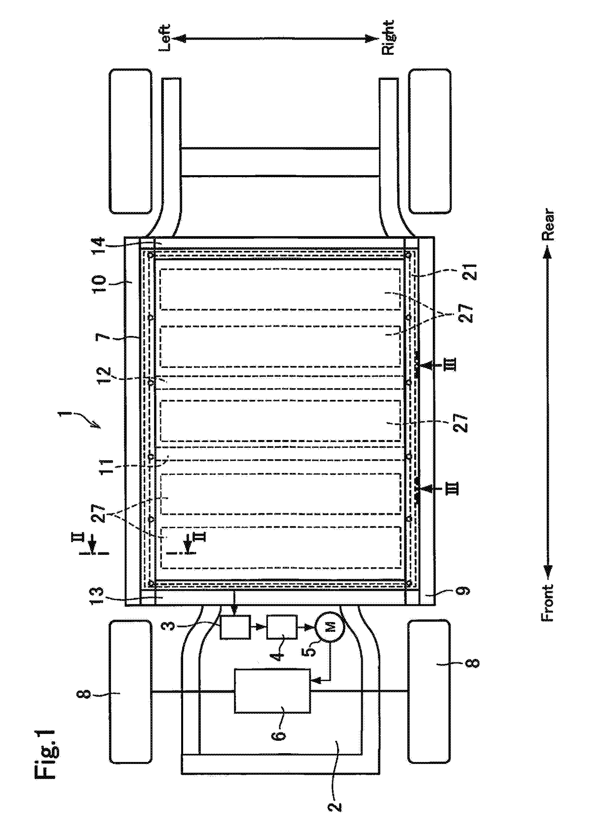
[0024]Hereinafter, embodiments of the present disclosure will be explained with reference to the accompanying drawings. Turning now to FIG. 1, there is shown one example of a bottom structure of a vehicle to which the battery mounting structure according to the present disclosure is applied. In the vehicle 1 shown in FIG. 1, a converter 3, an inverter 4, a motor 5 as an induction motor, and a power transmission unit 6 are arranged in a front compartment 2, and a battery pack 7 as a secondary battery is arranged under a floor panel. The converter 3 is adapted to increase a voltage from the battery pack 7, and to apply the voltage to the inverter 4 while stabilizing. The direct current power supplied from the battery pack 7 is converted into the alternate current power by the inverter 4, and further supplied to the motor 5 while controlling frequency. An output torque of the motor 5 is transmitted to drive wheels 8 through the power transmission unit 6 while being increased or decrea...


PUM

PropertyMeasurementUnit
widthaaaaaaaaaa
electrical energyaaaaaaaaaa
strengthaaaaaaaaaa

Abstract

A battery mounting structure is provided to prevent water intrusion into a clearance between a battery pack and a floor panel of a vehicle. The battery mounting structure comprises: frame members extending longitudinally on both sides of the vehicle; a floor panel disposed between the frame members; and a battery pack situated underneath the floor panel. A sealing member is interposed between a periphery of the battery pack and a portion extending from a member opposed to the battery pack, and a drain hole is formed in the sealing member to connect an inner side and an outer side of the sealing member.

Description

CROSS REFERENCE TO RELATED APPLICATIONS[0001]The present application claims the benefit of priority to Japanese Patent Application No. 2016-085567 filed on Apr. 21, 2016 with the Japanese Patent Office, the entire contents of which are incorporated herein by reference in its entirety.BACKGROUNDField of the Disclosure[0002]Embodiments of the present application relate to the art of a structure for mounting a battery for storing electrical energy in a vehicleDiscussion of the Related Art[0003]PCT international publication No. 2014 / 069270 describes one example of a battery mounting structure in vehicles. According to the teachings of PCT international publication No. 2014 / 069270, a battery pack is disposed on a vehicle-body strengthening member below a floor panel. Specifically, the strength member includes a pair of side members extending in the longitudinal direction of the vehicle, and a plurality of cross members for connecting the pair of side members in the width direction. The b...

Claims


Application Information

Patent Timeline
Patent Type & Authority Applications(United States)
IPC IPC(8): B60K1/04H01M2/10B62D25/20B60L11/18H01M50/204H01M50/249
CPCB60K1/04B62D25/20B60L11/1877H01M2220/20H01M2/1094B60K2001/0438H01M2/1083B60L3/00H01M50/249H01M50/204B62D25/025B62D25/2036B60L50/66Y02T10/70Y02E60/10H01M50/24
Inventor HARA, YASUHIRO
Owner TOYOTA JIDOSHA KK
Why Eureka
Try Eureka