High-pressure pump and fuel-supply system using same

a high-pressure pump and fuel-supply technology, which is applied in the direction of fuel injecting pumps, machines/engines, electric control, etc., can solve the problems of difficult smooth slide movement between the housing and the plunger, and high temperature of the high-pressure pump. to achieve the effect of limiting the seizing of the plunger

Active Publication Date: 2017-10-26
DENSO CORP
View PDF18 Cites 7 Cited by
  • Summary
  • Abstract
  • Description
  • Claims
  • Application Information

AI Technical Summary

Benefits of technology

[0007]It is an objective of the present disclosure to provide a high-pressure pump that can limit seizing of a plunger. It is another objective of the present disclosure to provide a fuel-supply system that includes the above high-pressure pump.
[0014]In the high-pressure pump of the present disclosure, the fuel of the fuel tank is suctioned into the pressurizing chamber through the inlet port, the leak chamber and the suction flow passage. The fuel, which is suctioned into the pressurizing chamber, is pressurized by the plunger and is discharged to an outside of the high-pressure pump. Thereby, when the high-pressure pump discharges the fuel of the high-pressure, the leaked fuel in the leak chamber is reliably discharged to the outside of the high-pressure pump through the suction flow passage, the pressurizing chamber and the outlet port together with the fuel of the fuel tank, which is introduced from the inlet port. In this way, it is possible to limit an increase of the temperature of the high-pressure pump, which is caused by long stay of the leaked fuel having the high temperature in the leak chamber, and thereby it is possible to limit evaporation of the fuel that is located between an inner wall of the pressurizing portion, which slides along an outer wall of the plunger, and the outer wall of the plunger.
[0015]Furthermore, the fuel stays in the leak chamber, the suction flow passage and the pressurizing chamber when the high-pressure pump is not discharging the fuel of the high pressure, i.e., when the discharging of the leaked fuel is not executed. When the temperature of the high-pressure pump is increased by the environment, in which the high-pressure pump is placed, the temperature of the fuel, which stays in the leak chamber, is increased. In the high-pressure pump of the present disclosure, the fuel can be supplied from the inlet port to the leak chamber by the suction check valve, but the fuel cannot be returned from the leak chamber to the inlet port. Therefore, the pressure of the fuel in the leak chamber is not excessively reduced, and thereby the fuel in, for example, the leak chamber is not evaporated. In this way, it is possible to limit the evaporation of the fuel, which is located in the gap between the inner wall of the pressurizing portion and the outer wall of the plunger, by the temperature increase of the high-pressure pump when the high-pressure pump is not discharging the fuel of the high pressure.
[0016]As discussed above, in the high-pressure pump of the present disclosure, the evaporation of the fuel, which is located in the gap between the inner wall of the pressurizing portion and the outer wall of the plunger, is limited regardless of whether the high-pressure pump is discharging the fuel of the high pressure. Thus, the smooth slide movement between the pressurizing portion and the plunger is ensured, and thereby the seizing of the plunger can be limited.

Problems solved by technology

Therefore, when the leaked fuel leaks into a space having a relatively low pressure, the temperature of the leaked fuel becomes high.
When this leaked fuel stays in this space for a relatively long period of time, the temperature of the high-pressure pump becomes high.
However, when the fuel in the gap is evaporated to form the fuel vapor, the smooth slide movement between the housing and the plunger becomes difficult.
Therefore, seizing may possibly occur between the inner wall of the housing and the outer wall of the plunger to possibly cause a damage of the high-pressure pump.
However, there are some disadvantages, such as an increase in the number of pipes for returning the leaked fuel and a difficulty of providing a space for installing these pipes depending on an install location of the high-pressure pump.
However, all of the leaked fuel cannot be discharged to the outside of the high-pressure pump, so that there is a possibility of that the temperature of the high-pressure pump is increased.
However, the temperature and the pressure of the fuel supplied to the low-pressure fuel injection valve may be changed by the temperature and the pressure of the leaked fuel.

Method used


Image

  • High-pressure pump and fuel-supply system using same
  • High-pressure pump and fuel-supply system using same
  • High-pressure pump and fuel-supply system using same

Examples


first embodiment

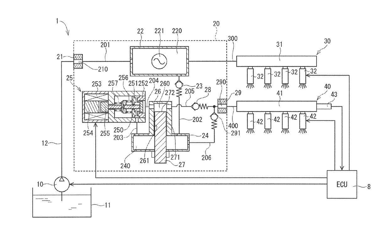
[0024]A fuel-supply system according to a first embodiment of the present disclosure will be described with reference to FIG. 1. The fuel-supply system 1 is a system that supplies fuel of one pressure and fuel of another pressure to an engine of a vehicle according to an operational state of the vehicle. The fuel-supply system 1 includes a low-pressure pump 10, a high-pressure pump 20, a low-pressure fuel supply device 30 serving as a low-pressure fuel supply device (low-pressure fuel supply means), a high-pressure fuel supply device 40 serving as a high-pressure fuel supply device (high-pressure fuel supply means), and a control device 8.

[0025]The low-pressure pump 10 is installed in an inside of a fuel tank 11 that stores fuel. The low-pressure pump 10 is connected to the high-pressure pump 20 through a fuel pipe 12 made of, for example, rubber. The low-pressure pump 10 pressurizes the fuel suctioned from the fuel tank 11 and discharges the pressurized fuel toward the high-pressur...

second embodiment

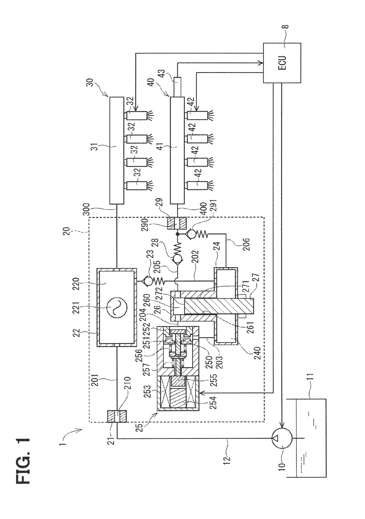
[0061]Next, a high-pressure pump according to a second embodiment of the present disclosure will be described. The second embodiment differs from the first embodiment with respect to the location of the pulsation damper, which damps the pressure pulsation of the fuel. In the following discussion, the portions, which are the same as those of the first embodiment, will be indicated by the same reference signs and will not be described redundantly for the sake of simplicity.

[0062]FIG. 2 is a schematic diagram of a fuel-supply system 2 according to the second embodiment. The fuel-supply system 2 is a fuel-supply system that is applicable even in a case where a certain amount of pressure fluctuation of the fuel in the low-pressure rail 31 caused by, for example, pressure pulsation of the low-pressure pump 10 and / or a pressure decrease caused by the fuel injection at the low-pressure fuel injection valve 32 is allowed.

[0063]In the fuel-supply system 2, a leak chamber pulsation damper 241 ...

third embodiment

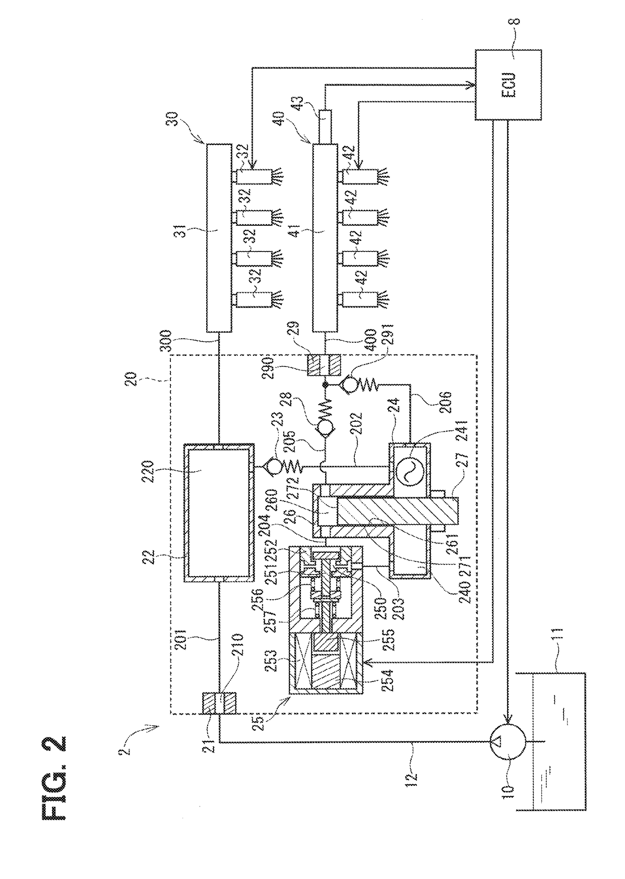
[0066]Next, a fuel-supply system according to a third embodiment of the present disclosure will be described with reference to FIG. 3. The third embodiment differs from the first embodiment with respect to the location of the low-pressure fuel pipe. In the following discussion, the portions, which are the same as those of the first embodiment, will be indicated by the same reference signs and will not be described redundantly for the sake of simplicity.

[0067]FIG. 3 is a schematic diagram of a fuel-supply system 3 according to the third embodiment. The fuel-supply system 3 is a fuel-supply system that is applicable even in a case where the pipe, which supplies the fuel to the low-pressure fuel supply device 30, cannot be branched from the high-pressure pump 20 due to, for example, a restriction in terms of space availability.

[0068]In the fuel-supply system 3, a flow branching portion 13 is placed in the fuel pipe 12. The flow branching portion 13 is connected to the low-pressure fuel...


PUM


Abstract

A high-pressure pump includes: a low-pressure chamber, into which low-pressure fuel discharged from a low-pressure pump flows; a pressurizing chamber, which pressurizes the low-low-pressure fuel; and a leak chamber, into which leaked fuel from the pressurizing chamber flows. The leaked fuel of the leak chamber is suctioned into and is pressurized in the pressurizing chamber together with the low-pressure fuel of the low-pressure chamber, so that the leaked fuel is discharged to an outside of the high-pressure pump as high-pressure fuel. Furthermore, a suction check valve, which is placed between the low-pressure chamber and the leak chamber, limits backflow of the leaked fuel of the leak chamber to the low-pressure chamber when the high-pressure pump does not supply the high-pressure fuel.

Description

CROSS REFERENCE TO RELATED APPLICATION[0001]This application is based on and incorporates herein by reference Japanese Patent Application No. 2014-246992 filed on Dec. 5, 2014.TECHNICAL FIELD[0002]The present disclosure relates to a high-pressure pump and a fuel-supply system using the same.BACKGROUND ART[0003]Previously, there is known a fuel-supply system that can supply fuel of different pressures to an internal combustion engine. For example, the patent literature 1 recites a fuel-supply system that includes: a low-pressure pump that pressurizes fuel of a fuel tank to a relatively low pressure and discharges the pressurized fuel; a high-pressure pump that pressurizes the fuel pressurized by the low-pressure pump to a relatively high pressure and discharges the pressurized fuel; a low-pressure fuel injection valve that injects the low-pressure fuel discharged from the low-pressure pump; and a high-pressure fuel injection valve that injects the high-pressure fuel discharged from t...

Claims


Application Information

Patent Timeline
Patent Type & Authority Applications(United States)
IPC IPC(8): F02D41/38F02M55/02F02M63/02F02M59/36F02D41/00F02M63/00
CPCF02D41/3836F02M55/02F02M59/367F02D2200/0602F02M63/00F02D41/00F02M63/02F02M63/029F02M59/366F02M59/442
Inventor NAKAOKA, MASAHARU
Owner DENSO CORP
Why Eureka
Try Eureka