Wide-angle lenses with low distortion
- Summary
- Abstract
- Description
- Claims
- Application Information
AI Technical Summary
Benefits of technology
Problems solved by technology
Method used
Image
Examples
example 1
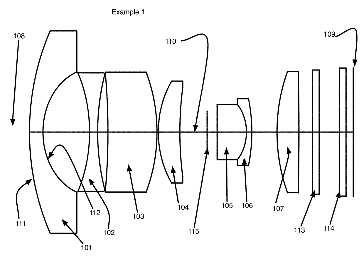
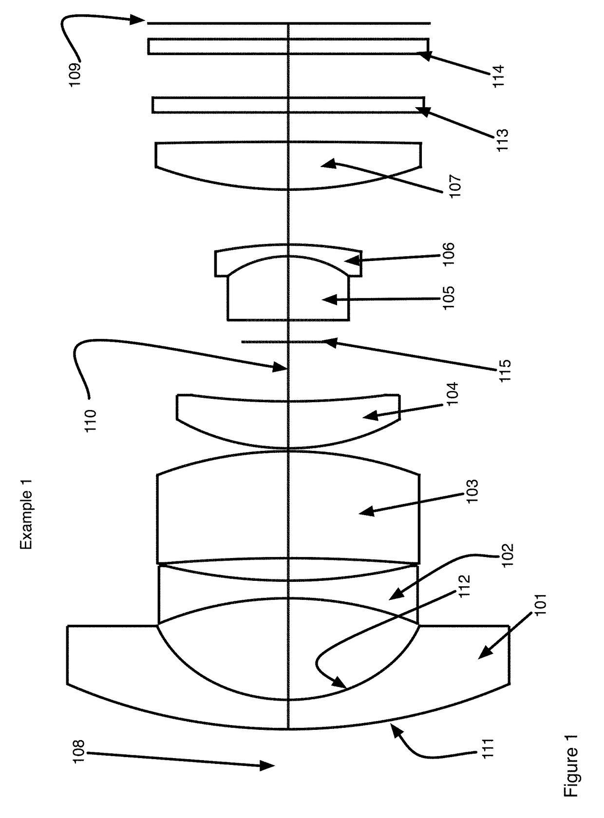
[0058]FIG. 1 shows the layout of Example 1. This design has a field angle of + / −75° (for a total field of view 150°) with a relative aperture of F / 2.8. The lens system is comprised sequentially from object end 108 to image plane 109 of seven lens elements 101-107. Each lens element is centered on the optical axis 110 of the lens system and each lens element is shown in a side cross-sectional view. Also shown are a filter 113 and a cover glass 114 for the image sensor 109. The first lens element 101 is a negative power meniscus lens having an object surface 111 and an image surface 112. All the other lens elements 102-107 similarly have object and image surfaces but these are not labeled so as to keep the Figure readable. The first lens element's object surface 111 is convex in all of the embodiments. The first lens elements image surface 112 is concave. The image surfaces 111, 112 are identified sequentially as surface 1 and surface 2 in Table 1 that gives the detailed prescription ...
example 2
[0065]FIG. 3 shows the optical layout of Example 2. This design has a field angle of + / −65 deg, or a 130 degree field of view and a relative aperture of F / 2.8. The design is comprised of four groups that total 8 lens elements 301-308 all centered upon the optical axis 310 and arranged sequentially from object to image. Group 1 is the first lens group facing the object space. This group is comprised of negative lens elements 301, 302. The first element (L1) 301 is a meniscus element with a convex surface facing the object. The second lens element 302 in the first group is also a meniscus lens with negative power. This first group has negative power. Both lens elements 301, 302 are spherical. Group 2 is the next group after group 1. This group has positive power. The lens elements 303, 304 of this group are important for lateral color correction. The elements are arranged such that there is a meniscus element 304 with positive power having a concave image-facing surface 313. This elem...
example 3
[0069]FIG. 5 shows the optical layout of Example 3. This is a fisheye lens with 195 deg total field of view having a F / 2.0 aperture. Again the example follows the general description for the first embodiment. The lens system is comprised of four lens groups that include a total of 9 lens elements 501-509. The groups are arranged sequentially from object to image centered upon the optical axis 510. Group 1 includes three lens elements 501-503. The first element 501 is a negative power lens with a convex surface facing the object. This first group has negative power. The second group includes two lens elements 504, 505. This group has positive power. The second element 505 is a meniscus element with positive power having a concave image-facing surface. This element 505 is the last element in this group facing the image space. An aperture stop 511 separates the lens elements 504, 505 of group 2 and the lens elements 506-508 of group 3. Group 3 comprises a doublet lens element structure...
PUM
 Abstract
Description
Claims
Application Information
 - R&D
- Intellectual Property
- Life Sciences
- Materials
- Tech Scout
- Unparalleled Data Quality
- Higher Quality Content
- 60% Fewer Hallucinations
Browse by: Latest US Patents, China's latest patents, Technical Efficacy Thesaurus, Application Domain, Technology Topic, Popular Technical Reports.
© 2025 PatSnap. All rights reserved.Legal|Privacy policy|Modern Slavery Act Transparency Statement|Sitemap|About US| Contact US: help@patsnap.com


