Progressive power lens

a technology of progressive power and lens, applied in the direction of optics, instruments, optical parts, etc., can solve the problems of inability to achieve the reduction of lens thickness, the central portion of the lens becomes large, and the problem of arising as described below

Active Publication Date: 2005-12-29
SEIKO OPTICAL PROD TRADING AS SEIKO OPTICAL PROD +1
View PDF7 Cites 0 Cited by
  • Summary
  • Abstract
  • Description
  • Claims
  • Application Information

AI Technical Summary

Benefits of technology

[0007] The present invention is advantageous in that it provides an progressive power lens configured such that the lens has a positive power in a distance portion and that the thickness of a central portion there of is small while keeping a meniscus shape.

Problems solved by technology

Such a view is ascribable to the fact that if a back surface of a spectacle lens is a convex surface, problems as described below may arise.
However, if the above mentioned design manner is adopted in designing a progressive power lens having a positive power in a distance portion thereof, a thickness of the central portion of the lens becomes large, and thereby the reduction of the lens thickness can not be attained.

Method used


Image

  • Progressive power lens
  • Progressive power lens
  • Progressive power lens

Examples


second example

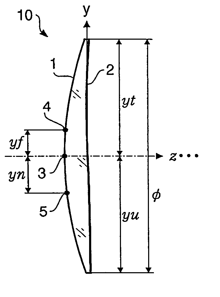
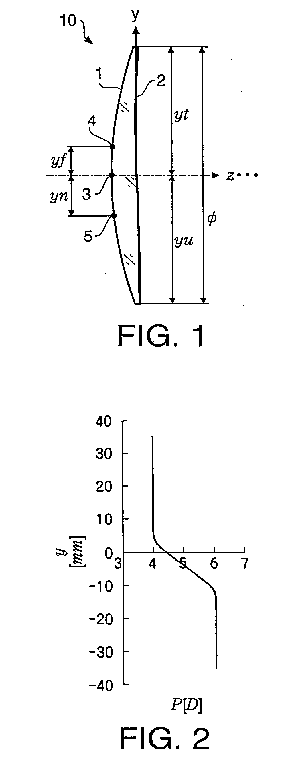
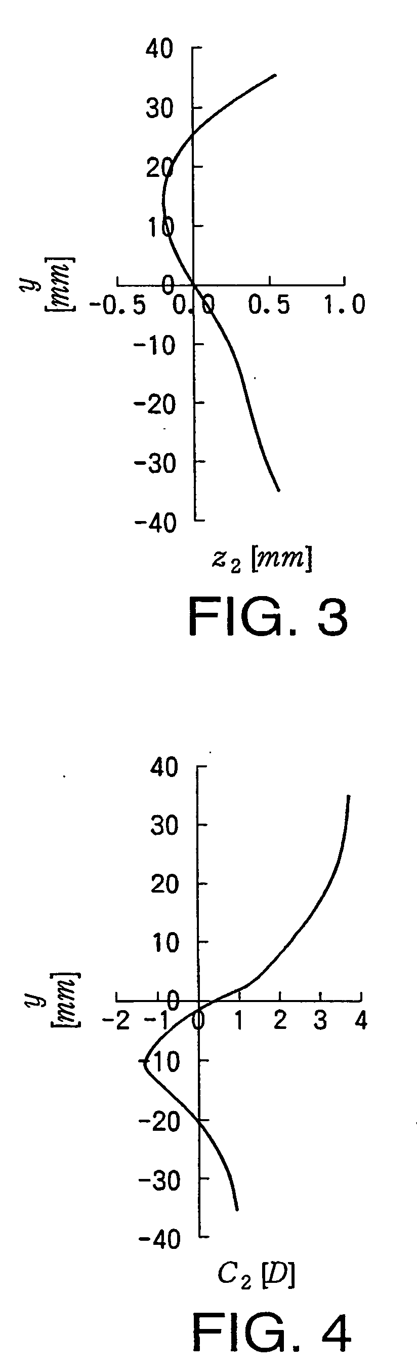
[0093] A progressive power lens according to a second example of the embodiment will be described. The lens according to the second example is also referred to as the lens 10. A vertical cross-section of the lens 10 according to the second example is shown in FIG. 9. FIG. 10 is a graph illustrating change of a transmission power of the lens 10 according to the second example. FIG. 11 is a graph illustrating change of a sag amount z2(y) of the back surface 2 of the lens 10 according to the second example. FIG. 12 is a graph illustrating change of the curvature of the back surface 2 along the vertical cross-section. A numerical configuration of the lens 10 obtained from the graphs of FIGS. 9 to 12 is shown in Table 4.

TABLE 4Pf6.00[D]ADD3.00[D]Refractive index1.60D17.14[D]C2(yf)2.94[D]C2(yn)−1.51[D]z2(yt)0.75[mm]z2(yu)0.75[mm]z2(0)0.00[mm]

[0094] As shown in FIGS. 11 and 12, the back surface 2 has a convex shape portion protruding to an eye side in the vicinity of the near reference p...

third example

[0099] A progressive power lens according to a third example of the embodiment will be described. The lens according to the third example is also referred to as the lens 10. The lens 10 according to the third example has a property of correcting astigmatism. A vertical cross-section of the lens 10 according to the third example is shown in FIG. 17. FIG. 18 shows is a contour map representing a surface shape of the back surface 2 by contour lines drawn at intervals of 0.5 mm. In FIG. 18 (and in similar graphs of FIGS. 23, 38 and 44), an x-axis represents an axis which passes through an intersection point of the back surface 2 and the z-axis and is perpendicular to the y-axis and z-axis. That is, the x-axis defined as a horizontal line in a state where a wearer wears the lens.

[0100] A minimum curvature C2min, a maximum curvature C2max and a direction γ of the minimum curvature cross section, which are obtained when the back surface 2 is approximated by a toric surface, are shown in T...

fourth example

[0110] A progressive power lens according to a fourth example of the embodiment will be described. The lens according to the fourth example is also referred to as the lens 10. A vertical cross-section of the lens 10 according to the fouth example is shown in FIG. 27. The lens 10 according to the fourth example is configured such that both of the front and back surfaces are progressive surfaces. In this example, the first half of the addition power is provided by a surface power of the front surface 1, while the second half of the addition power and the correction for aberrations are provided by a progressive surface of the back surface 2.

[0111]FIG. 28 is a graph illustrating change of a transmission power of the lens 10 according to the fourth example. FIG. 29 is a graph illustrating a sag amount z2(y) of the back surface 2 of the lens 10 according to the fourth example. FIG. 30 is a graph illustrating change of the curvature of the front surface 1 along the vertical cross-section....


PUM


Abstract

A progressive power lens having a positive vertex power in a distance portion is provided. At least a back surface of the progressive power lens is configured as a progressive surface. The progressive power lens satisfies a condition: Pf+ADD3<D1<Pf+ADD(1)
where Pf represents a vertex power in the distance portion along a vertical cross-section, ADD represents an addition power, and D1 represents a surface power of a front surface.

Description

INCORPORATION BY REFERENCE [0001] This application claims priority of Japanese Patent Application No. 2004-188851, filed on Jun. 25, 2004, the entire subject matter of the application being incorporated herein by reference. BACKGROUND OF THE INVENTION [0002] The present invention relates to a progressive power lens configured to have positive power in a distance portion and to have a progressive surface formed at least on an back surface (an eye side surface) thereof. [0003] Progressive power lenses have been widely used for correction of presbyopia. In order to secure a high degree of processing flexibility and to secure a wide clear vision area, it is preferable that a progressive power lens is configured such that a progressive surface is formed on a back surface of the lens. An example of such a progressive power lens is disclosed in International publication No. WO 97 / 19382 (hereafter, referred to as a document 1). [0004] It is preferable that a spectacle lens is formed to be a...

Claims


Application Information

Patent Timeline
Patent Type & Authority Applications(United States)
IPC IPC(8): G02C7/02G02C7/06
CPCG02C7/068G02C7/061
Inventor SHIRAYANAGI, MORIYASU
Owner SEIKO OPTICAL PROD TRADING AS SEIKO OPTICAL PROD
Why Eureka
Try Eureka