Telephoto lens system

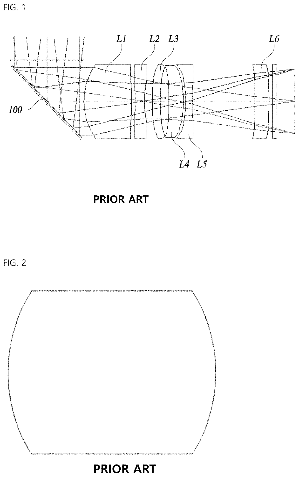
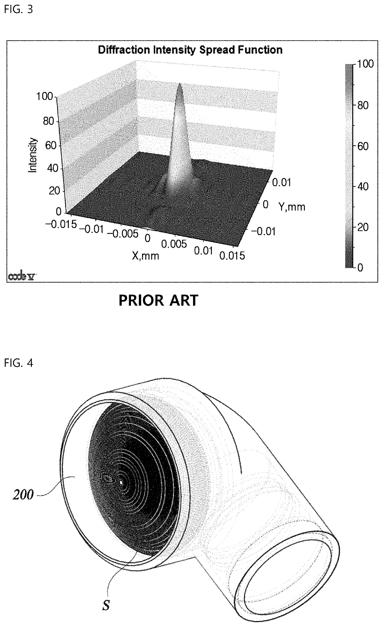
a telephoto lens and lens body technology, applied in the field of telephoto lens systems, can solve the problems of reducing resolution by diffraction, difficult mounting of telephoto lenses in thin devices such as smartphones, and the inability to mount lenses with a focal length of 10 mm or more, so as to achieve the effect of minimizing the height of the entire lens system

Active Publication Date: 2021-06-15
SEKONIX
View PDF1 Cites 0 Cited by
  • Summary
  • Abstract
  • Description
  • Claims
  • Application Information

AI Technical Summary

Benefits of technology

[0010]Accordingly, the present invention has been made keeping in mind the above problems occurring in the related art, and the present invention is intended to propose a telephoto lens system having a long effective focal length and having a structure formed by a refractor provided between a second and a third lens so as to bend an optical axis, thus minimizing the height of the entire lens system.
[0025]The present invention relates to a telephoto lens system having a total of five lenses, wherein each lens is evenly distributed positive and negative refractive power. The telephoto lens system realizes smallness, lightness, and correction of distortion, and the effective focal length of the total lens system is 11 mm or more. Also, by providing a reflector between the second lens and the third lens to form a structure to bend the optical axis, there is an effect that can be effectively applied to a small camera module, in particular, a smartphone by minimizing the height of the entire lens system.

Problems solved by technology

This length limitation makes the telephoto lens challenging to mount in a thin device such as a smartphone.
In particular, a lens with a focal length of 10 mm or more cannot be mounted because the length of the lens is about 10 mm in proportion to the focal length, which is much thicker than the thickness of a smartphone.
However, when cutting off the upper and lower portions, there is a problem in that the resolution should be reduced by diffraction, as shown in FIG. 3.

Method used


Image

  • Telephoto lens system
  • Telephoto lens system
  • Telephoto lens system

Examples


embodiment 1

[0061]FIG. 7 shows a first embodiment of a wide-angle lens system for high resolution according to the present invention.

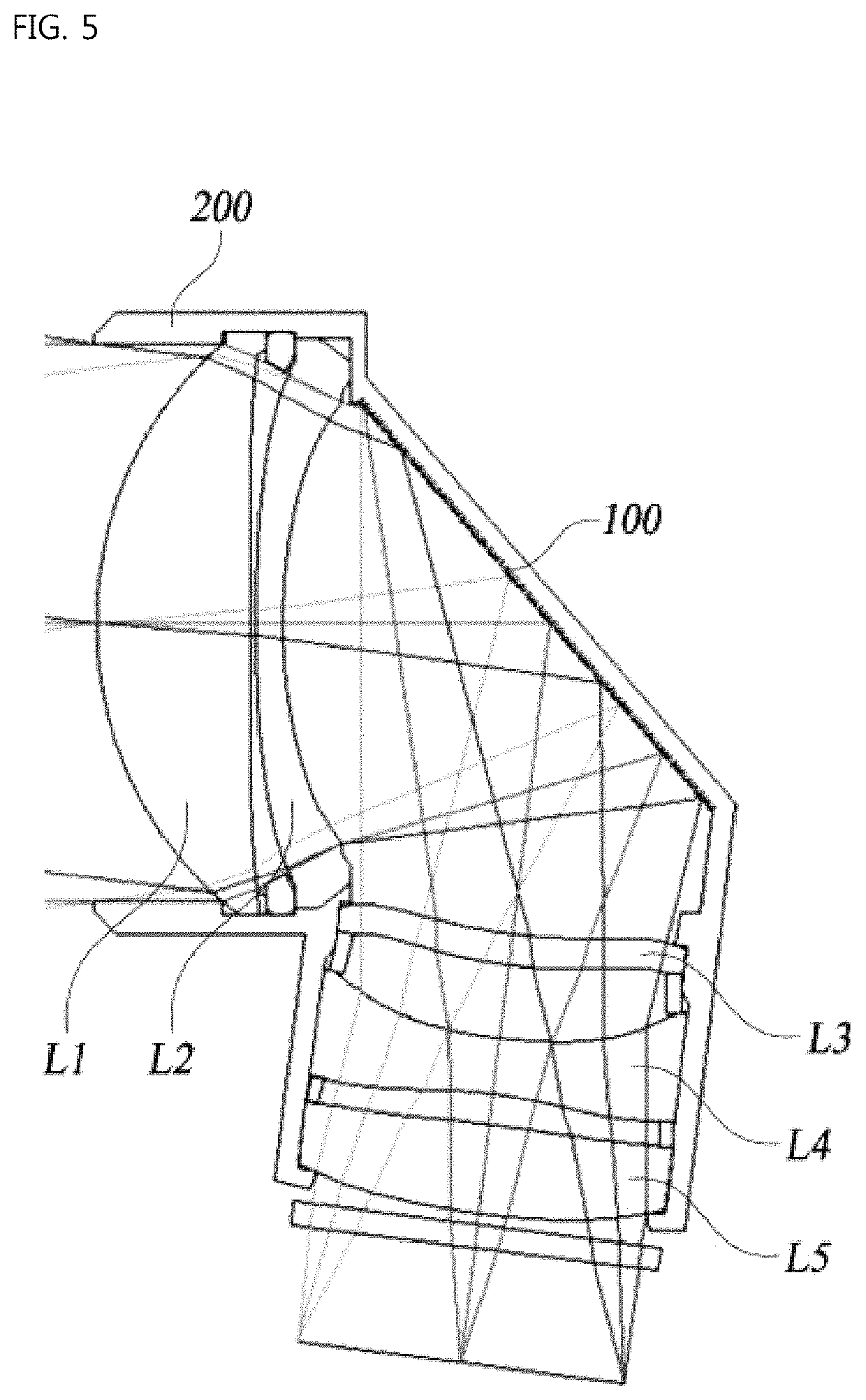
[0062]As shown, the first lens L1, the second lens L2, the third lens L3, the fourth lens L4, and the fifth lens L5 are arranged in sequence from the focal object side along the optical axis.

[0063]Table 1 shows numerical data of the lenses configuring the optical system according to the first embodiment of the present invention.

[0064]

TABLE 1Surface RDY Nd Vd (Surface (Curvature THI (Refractive (Abbe Number) Radius) (Thickness) Index) Number)FOCAL INFINITY INFINITY OBJECT STOP INFINITY 0.01 2 3.338 1.41 1.544 56 3 −127.32417 0.05 4 12.200 0.25 1.661 20.4 5 4.882 2.44 MIRROR INFINITY −2.80 7 5.835 −0.28 1.535 56 8 4.963 −0.66 9 6.768 −0.50 1.544 56 10 −3.973 −0.28 11 −12.654 −0.80 1.635 23.9 12 10.132 −0.10 13 INFINITY −0.21 1.517 64.2 14 INFINITY −1.03 IMAGE INFINITY 0.00

[0065]As shown in FIG. 7, the first lens L1, the second lens L2, the third lens L3, the fourth ...

embodiment 2

[0075]FIG. 9 shows a second embodiment of a wide-angle lens system for high resolution according to the present invention.

[0076]As shown, the first lens L1, the second lens L2, the third lens L3, the fourth lens L4, and the fifth lens L5 are arranged in sequence from the focal object side along the optical axis.

[0077]Table 3 shows numerical data of the lenses configuring the optical system according to the second embodiment of the present invention.

[0078]

TABLE 3Surface RDY Nd Vd (Surface (Curvature THI (Refractive (Abbe Number) Radius) (Thickness) Index) Number)FOCAL INFINITY INFINITY OBJECT STOP INFINITY 0.01 2 3.244 1.49 1.544 56 3 301.95596 0.05 4 9.860 0.25 1.661 20.4 5 4.350 2.60 MIRROR INFINITY −2.70 7 5.609 −0.25 1.535 56 8 4.804 −0.53 9 6.305 −0.37 1.544 56 10 −4.350 −0.36 11 −8.017 −1.00 1.635 23.9 12 22.416 −0.10 13 INFINITY −0.21 1.517 64.2 14 INFINITY −1.04 IMAGE INFINITY 0.00

[0079]Aspheric coefficients having data of the above lenses from Equation 1 are shown in Table 4...

embodiment 3

[0086]FIG. 11 shows a third embodiment of a wide-angle lens system for high resolution according to the present invention.

[0087]As shown, the first lens L1, the second lens L2, the third lens L3, the fourth lens L4, and the fifth lens L5 are arranged in sequence from the focal object side along the optical axis.

[0088]Table 5 shows numerical data of the lenses configuring the optical system according to the third embodiment of the present invention.

[0089]

TABLE 5Surface RDY Nd Vd (Surface (Curvature THI (Refractive (Abbe Number) Radius) (Thickness) Index) Number)FOCAL INFINITY INFINITY OBJECT STOP INFINITY 0.01 2 3.368 1.34 1.544 56 3 −44.17484 0.05 4 15.040 0.26 1.661 20.4 5 5.255 2.38 MIRROR INFINITY −3.00 7 5.629 −0.26 1.535 56 8 4.697 −0.34 9 6.160 −0.73 1.544 56 10 −3.629 −0.34 11 −5.455 −0.88 1.635 23.9 12 2000.000 −0.10 13 INFINITY −0.21 1.517 64.2 14 INFINITY −0.72 IMAGE INFINITY 0.00

[0090]Aspheric coefficients having data for the above lenses from Equation 1 are shown in Tabl...


PUM

PropertyMeasurementUnit
angleaaaaaaaaaa
focal lengthaaaaaaaaaa

Abstract

A telephoto lens system having a plurality of lenses toward a focal object is proposed. The system includes a first lens with a positive refractive power, a second lens with a negative refractive power, a third lens with a negative refractive power, a fourth lens with a negative refractive power, and a fifth lens with a positive refractive power. A refractor bending an optical axis is provided between the second lens and the third lens. The angle (A) between the optical axes of the second lens and the third lens satisfies 80°≤A≤86°. A barrel surrounding the first lens is provided by protruding more toward the focal object than the first lens. The inner diameter of the barrel is smaller than or equal to the effective diameter of the first lens, and a stop is arranged toward the focal object of the first lens.

Description

CROSS REFERENCE TO RELATED APPLICATION[0001]The present application claims priority to Korean Patent Application No. 10-2019-0038555, filed Apr. 2, 2019, the entire contents of which is incorporated herein for all purposes by this reference.BACKGROUND OF THE INVENTIONField of the Invention[0002]The present invention relates generally to a telephoto lens system. More particularly, the present invention relates to a telephoto lens system, which has a long effective focal length and includes a reflector between a second lens and a third lens to form a structure for bending an optical axis, thereby minimizing the height of the entire lens system.Description of the Related Art[0003]Generally, a telephoto lens allows a person to magnify and view an object at a far distance, and to magnify and photograph the focal object at a viewing angle narrower than a normal viewing angle.[0004]Since the telephoto lens has a long focal length, a length from a vertex of a front surface of a lens to an i...

Claims


Application Information

Patent Timeline
Patent Type & Authority Patents(United States)
IPC IPC(8): G02B13/02G02B13/00G02B5/08G02B1/04G02B9/60
CPCG02B13/02G02B1/041G02B5/08G02B9/60G02B13/0045G02B13/0055G02B13/0065G02B3/02G02B23/2407
Inventor CHOI, SOON CHEOLNOH, KI YOUNNAM, SEUNG NAMKIM, SUNG NYUN
Owner SEKONIX
Why Eureka
Try Eureka