Electronic apparatus and coordinates detection method

a technology of coordinate detection and electronic equipment, applied in the direction of instruments, electric digital data processing, computing, etc., can solve the problems of hardly detected hardly used capacitive touch panels, and inability to detect distortion of transparent members, so as to prevent the generation of erroneous operations and reduce the operability of active pen.

Active Publication Date: 2017-10-26
PANASONIC INTELLECTUAL PROPERTY MANAGEMENT CO LTD
View PDF2 Cites 6 Cited by
  • Summary
  • Abstract
  • Description
  • Claims
  • Application Information

AI Technical Summary

Benefits of technology

[0010]According to the disclosure, it is possible to prevent generation of an erroneous operation due to water droplets or the like and reduction of operability of the active pen.

Problems solved by technology

However, in the capacitive touch panel, there is a possibility that malfunction occurs when a conductor such as water droplets and the like is attached on a surface thereof.
Therefore, it is unlikely that the capacitive touch panel is used in rainy weather.
However, in a case where the active pen is used in the technology, since the load of an operation by the active pen is very light, there are problems that distortion of the transparent member is hardly detected and operability is reduced.

Method used


Image

  • Electronic apparatus and coordinates detection method
  • Electronic apparatus and coordinates detection method
  • Electronic apparatus and coordinates detection method

Examples


modification example 1

[0129]In the embodiment, the operation example of electronic apparatus 1 is described by using a flow of FIG. 11. However, the operation example of electronic apparatus 1 may be a flow of an operation illustrated in FIG. 12. FIG. 12 is different from FIG. 11 in that step S207 is performed, instead of step S107 of FIG. 11.

[0130]In step S207, control unit 6 determines whether or not the amount of distortion detected by pressure sensor 3 exceeds the valid amount of distortion and a time equal to or greater than a designated time elapses from the detection of the release of the validated coordinates indicated by the active pen. Here, for example, the designated time is the same as the designated time described in step S109 of FIG. 11.

[0131]In a case where a determination result of step S207 is NO, the flow returns to step S101, and in a case where the determination result of step S207 is YES, the flow proceeds to step S108.

[0132]That is, after the coordinates indicated by the active pen...

modification example 2

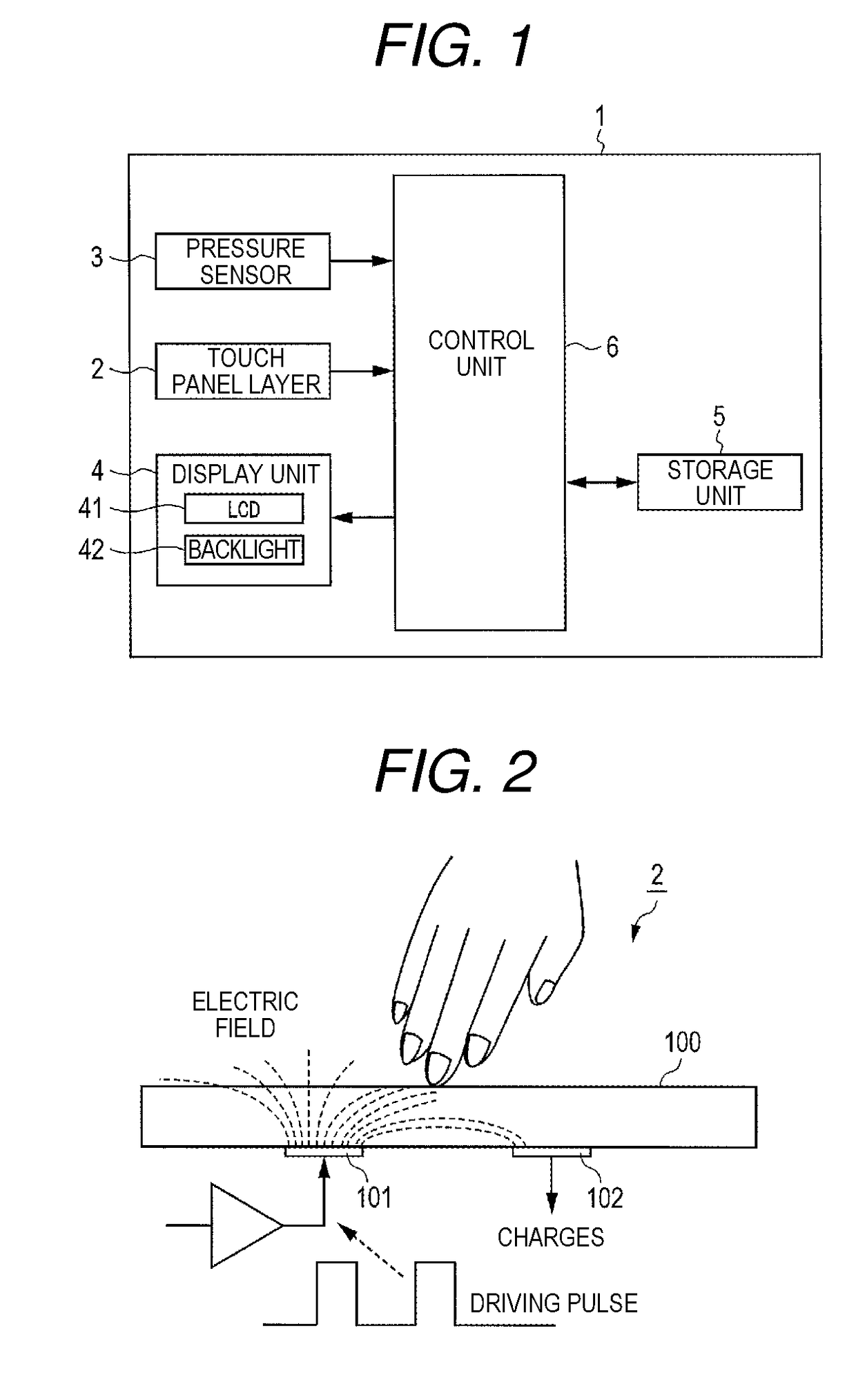
[0134]In addition, in the embodiment, Disposition Example 1 of touch panel layer 2, pressure sensor 3, and display unit 4 is described by using FIG. 6 and FIG. 7.

[0135]However, the Disposition Example is not limited thereto. Hereinafter, each of Disposition Examples 2 to 10 other than Disposition Example 1 will be described with reference to the drawings.

[0136]FIG. 13 is a side sectional view of electronic apparatus 1 illustrating Disposition Example 2. As illustrated in FIG. 13, touch panel layer 2, display unit 4 (LCD 41 and backlight 42), pusher (plunger) 21, pressure sensor 3, and elastic member 22 are sequentially disposed under glass 11.

[0137]In FIG. 13, pusher 21 is disposed between backlight 42 and pressure sensor 3. An end of pusher 21 is in contact with a surface of backlight 42, and the other end of pusher 21 is fixed into a surface of pressure sensor 3. Recess portion 23 is formed in framework portion 12 (example of a part of housing 10) of housing 10. Elastic member 22 ...

modification example 3

[0156]In electronic apparatus 1 of the embodiment, in a case where pressure sensor 3 does not detect distortion when touch panel layer 2 determines two-dimensional coordinates, it is also possible for control unit 6 to determine that the conductor such as water droplet and the like is attached on the touch panel surface. In this case, for example, control unit 6 may be also controlled to display the display indicating a determination result on display unit 4.


PUM

PropertyMeasurementUnit
elapsed timeaaaaaaaaaa
distanceaaaaaaaaaa
transparentaaaaaaaaaa

Abstract

An electronic apparatus includes a display unit that displays information, a capacitive touch panel layer that transmits display of the display unit, and detects coordinates indicated by an indicator separated from a surface in a predetermined distance, a glass that protects the touch panel layer, and transmits the display of the display unit, a pressure sensor that detects distortion of the glass, and a control unit that validates and invalidates the coordinates detected by the touch panel layer. The control unit validates the coordinates detected by the touch panel layer in a case where the indicator is an active pen, and validates the coordinates most recently detected by the touch panel layer, when a predetermined amount of distortion is detected by the pressure sensor, in a case where the indicator is other than an active pen.

Description

BACKGROUND1. Technical Field[0001]The present disclosure relates to an electronic apparatus on which a touch panel is mounted and a coordinates detection method.2. Description of the Related Art[0002]An electronic apparatus on which a touch panel is mounted such as a smartphone, a tablet, and the like is spread. However, in such an electronic apparatus, there is also provided an apparatus with a capacitive touch panel. The capacitive touch panel can receive not only a “touch operation” which is performed by a finger of a bare hand or a pointing device (object having conductivity) directly being in contact with a surface thereof, but also a “hover operation” which is performed by the finger at a predetermined height from the surface thereof without the finger of the bare hand being in contact with the surface of the touch panel. With this, users can perform an operation by using not only the bare hand or the pointing device, but also a gloved finger.[0003]For example, as the pointing...

Claims


Application Information

Patent Timeline
Patent Type & Authority Applications(United States)
IPC IPC(8): G06F3/041G02F1/1333G06F3/044
CPCG06F3/0416G06F3/044G06F3/0412G02F2201/50G06F2203/04105G06F2203/04101G02F1/13338G06F3/04162G06F3/0442G06F3/0443
Inventor TAKANO, TOMOKIYAMAGUCHI, TAKESHI
Owner PANASONIC INTELLECTUAL PROPERTY MANAGEMENT CO LTD
Why Eureka
Try Eureka