Electronic alignment using signature emissions for backhaul radios
What is Al technical title?
Al technical title is built by PatSnap Al team. It summarizes the technical point description of the patent document.
a backhaul radio and signature emission technology, applied in the field of data networking, can solve the problems of time-consuming and costly directive antennas associated with such products, requiring skilled technicians, and affecting the operation of the backhaul radio
Active Publication Date: 2017-10-26
COMS IP HLDG LLC
View PDF2 Cites 45 Cited by
Summary
Abstract
Description
Claims
Application Information
AI Technical Summary
This helps you quickly interpret patents by identifying the three key elements:
Problems solved by technology
Method used
Benefits of technology
Problems solved by technology
However, the installation and maintenance of the alignment of the typically high gain and highly directive antennas associated with such products prove time consuming and costly, requiring skilled technicians.
In some installations, use of an optical alignment scope can be problematic because mechanical clearance to utilize the scope may not be possible due to mechanical obstruction.
For example, an installer may not have the room to fit between an interfering structure such as a wall and the optical alignment scope viewing port.
In some installations, physical obstructions around almost every portion of the radio and parabolic reflector may be present, making the use of an optical alignment scope virtually impossible.
However, if the crane or the water tower depicted in FIG. 2A were to impinge upon the Fresnel zone clearance area, reflections or diffraction of transmitted signal from these structures may create multiple propagation paths or “multipath.” Such multipath may cause fading or undesirable channel propagation characteristics for the line of sight communication link.
However, as can be understood by one of ordinary skill in the art, such manual searching without guidance as to which direction, within the available degrees of freedom, adjustments should be made can result in lengthy and imprecise process during the installation.
Such an installation process requires skilled labor in the form of experienced technicians, which may be in limited availability resulting in limitations in the ability to quickly deploy large numbers of the poin...
Method used
Image
Click on the blue label to locate the original text in one second.
Reading with bidirectional positioning of images and text.
Examples
Embodiment Construction
[0100]Aspects of the present inventions provide for significant simplification of the installation processes in specific embodiments.
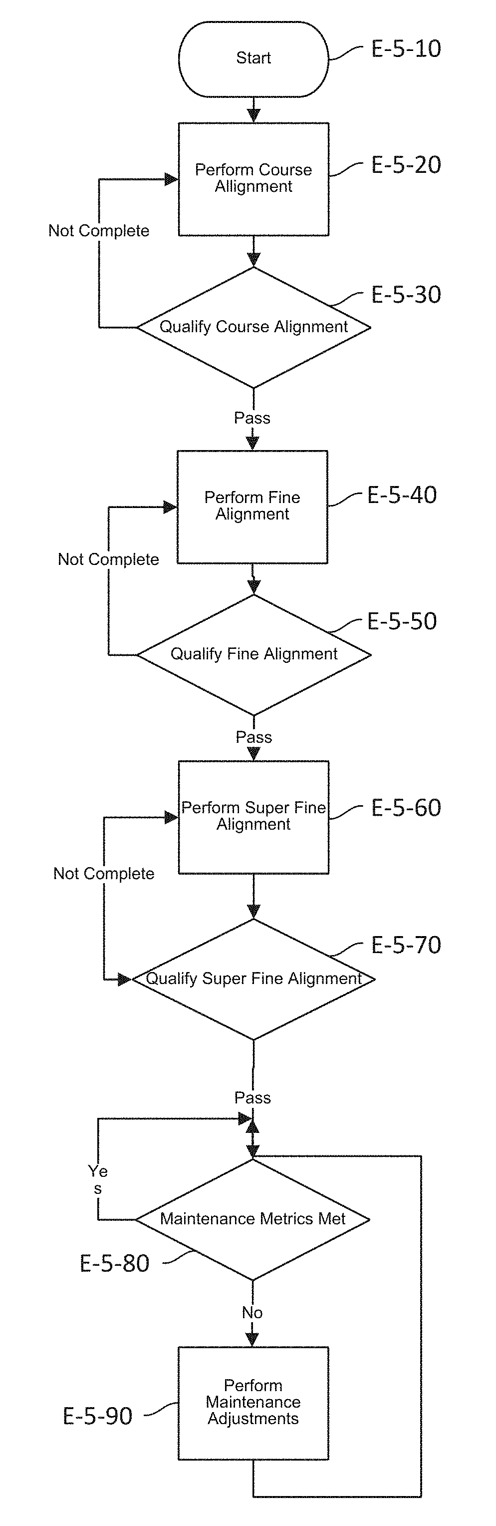
[0101]FIG. 5 is an exemplary flow diagram of an embodiment of a multi-stage point-to-point radio antenna alignment procedure for use in initial alignment and link parameter maintenance, including ongoing alignment in some embodiments. Other embodiments may include point to multipoint radios, of other configurations. The process is started in Step E-5-10 with a technician performing initial mounting of the antenna and radio hardware. Next, in Step E-5-20 a course alignment is performed utilizing one or more of the embodiments of the present invention, which will be discussed in more detail, associated with subsequent figures. In one embodiment, an alignment-aiding device may be utilized which may be integrated with and inside the physical enclosure and housing of the point-to-point radio or may be mounted to the exterior of the radio. The electronics ma...
PUM
Abstract
A backhaul radio is disclosed that includes one or more antenna structures collectively having a plurality of selectable radiation patterns for detecting alignment signals; one or more receivers configured to receive the alignment signals from the one or more antenna structures and provide received signals; one or more processors for processing the received signals to determine signal properties, wherein at least one of the one or more processors are coupled to at least one of the one or more receivers to receive said received signals; and an interface to couple at least one of the one or more processors to an alignment assisting device. The alignment assisting device coordinates between the backhaul radio and the second backhaul radio during the alignment process. The alignment assisting device further provides an indication of an improved alignment adjustment to a user of the alignment assisting device.
Description
CROSS-REFERENCE TO RELATED APPLICATIONS[0001]The present application is a Continuation-in-part of U.S. patent application Ser. No. 15 / 403,090, filed on Jan. 10, 2017, which is a Continuation of U.S. patent application Ser. No. 15 / 084,867, filed on Mar. 30, 2016, now U.S. Pat. No. 9,577,733, which is a Continuation of U.S. patent application Ser. No. 14 / 839,018, filed on Aug. 28, 2015, now U.S. Pat. No. 9,325,398, which is a Continuation of U.S. patent application Ser. No. 13 / 934,175, filed on Jul. 2, 2013, now U.S. Pat. No. 9,179,240, which is a Continuation of U.S. patent application Ser. No. 13 / 371,346, filed on Feb. 10, 2012, now U.S. Pat. No. 8,502,733, the disclosures of which are hereby incorporated herein by reference in their entireties.[0002]The present application is also a Continuation-in-part of U.S. patent application Ser. No. 15 / 398,174, filed on Jan. 4, 2017, which is a Continuation of U.S. patent application Ser. No. 15 / 165,504, filed May 26, 2016, now U.S. Pat. No. ...
Claims
Application Information
Patent Timeline
Application Date:The date an application was filed.
Publication Date:The date a patent or application was officially published.
First Publication Date:The earliest publication date of a patent with the same application number.
Issue Date:Publication date of the patent grant document.
PCT Entry Date:The Entry date of PCT National Phase.
Estimated Expiry Date:The statutory expiry date of a patent right according to the Patent Law, and it is the longest term of protection that the patent right can achieve without the termination of the patent right due to other reasons(Term extension factor has been taken into account ).
Invalid Date:Actual expiry date is based on effective date or publication date of legal transaction data of invalid patent.