Powered working machine
a working machine and power technology, applied in the field of powered working machines, can solve problems such as disconnection of coils or the like, and achieve the effects of suppressing transmission of vibrations to the control board, reducing vibrations of the housing, and suppressing transmission of vibrations to the board
- Summary
- Abstract
- Description
- Claims
- Application Information
AI Technical Summary
Benefits of technology
Problems solved by technology
Method used
Image

Examples
embodiment 1
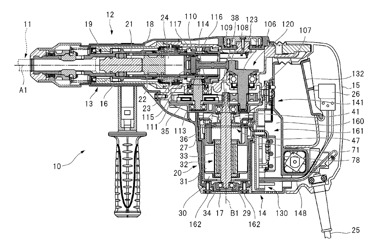
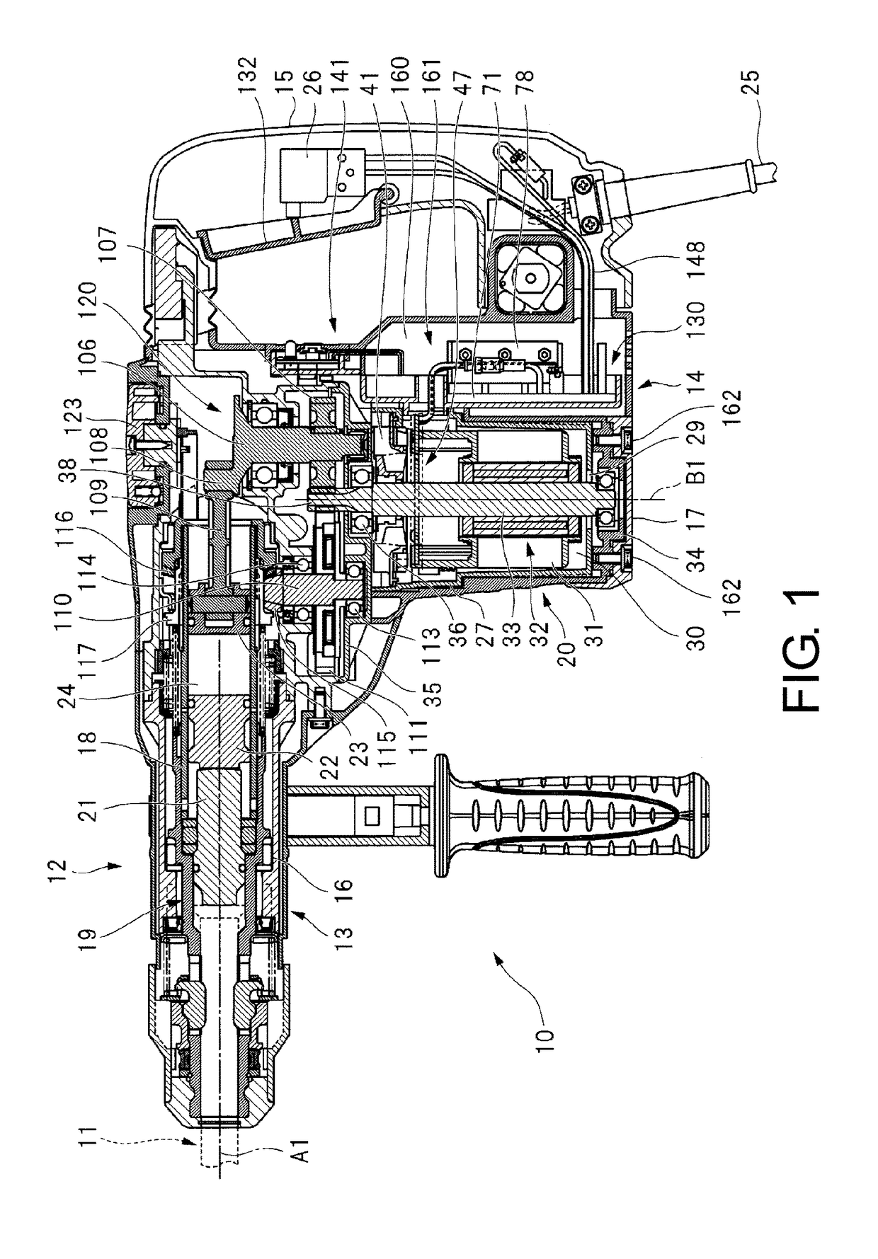
[0044]A powered working machine in Embodiment 1 of the disclosure will be described with reference to FIG. 1 to FIG. 7. An electric working machine 10 serving as the powered working machine is also referred to as a hammer drill. The electric working machine 10 is used to perform drilling or the like on a target such as concrete, a stone material, or the like.
[0045]The electric working machine 10 includes a working machine main body 12, and the working machine main body 12 is assembled by fixing a cylinder housing 13, an intermediate case 14, a handle 15, a motor housing 20 and a bottom cover 17 to each other. The bottom cover 17 is fixed to the motor housing 20 by a screw member 162. The bottom cover 17 is disposed adjacent to the motor housing 20 in a direction along an axis B1. Vent holes 17a passing through the bottom cover 17 are provided.
[0046]The cylinder housing 13 is formed in a cylindrical shape, and a cylinder 18 having a cylindrical shape is installed in the cylinder hous...
embodiment 2
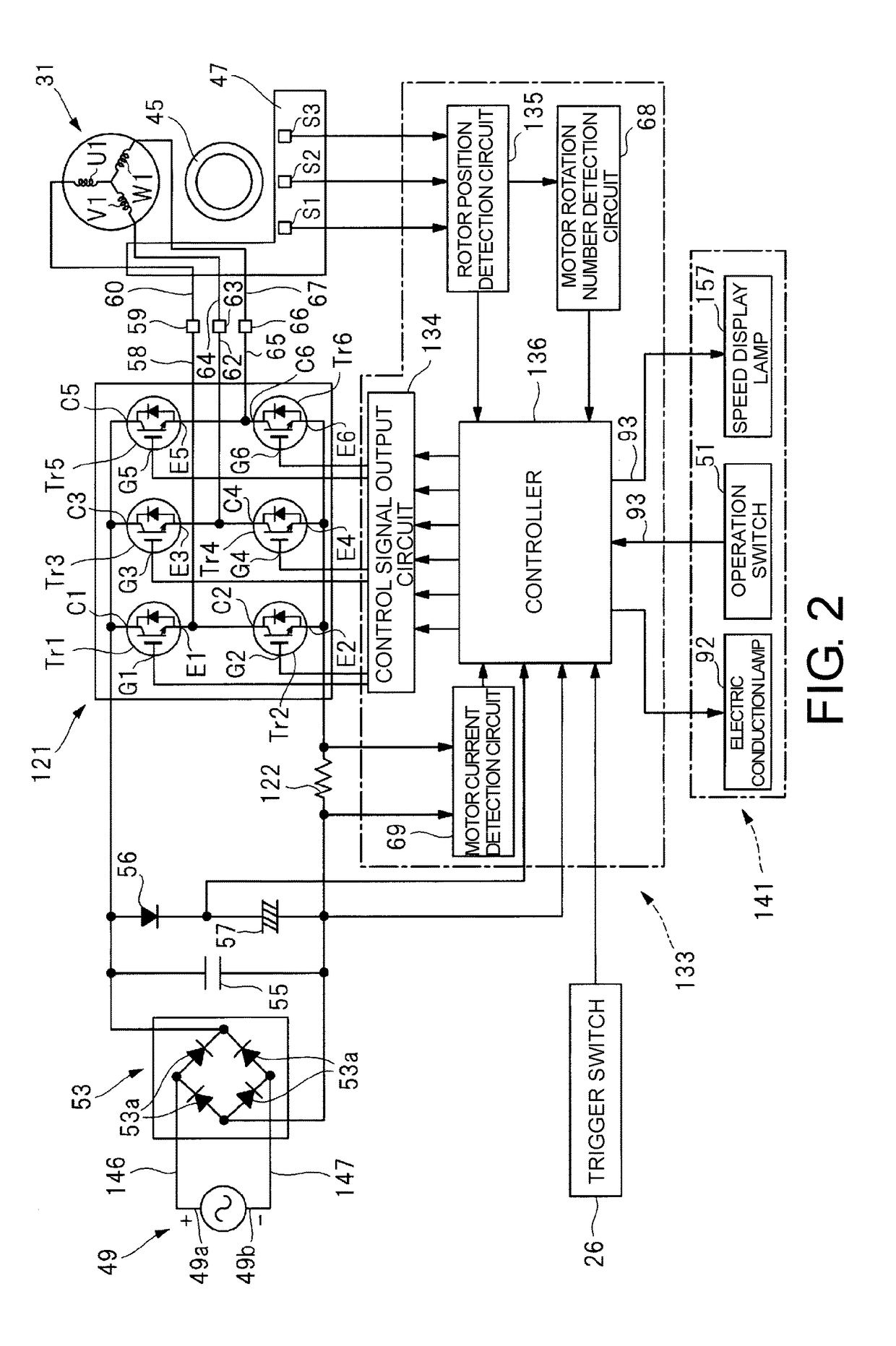
[0102]A powered working machine in Embodiment 2 of the disclosure will be described with reference to FIG. 8. Comparing FIG. 8 with FIG. 1, a disposition position of the control unit 130 of the electric working machine 10 differs. The electric working machine 10 shown in FIG. 8 uses the control circuit of FIG. 2. The control unit 130 shown in FIG. 8 is disposed between the brushless motor 30 and the bottom cover 17 in the direction along the axis B1. The cover 160 shown in FIG. 3 is not provided in FIG. 8. In addition, the control board 71 is disposed in a direction crossing the axis B1 when seen in a front view of the electric working machine 10. A concave section 164 is formed in an inner surface of the bottom cover 17, and the board case 82 is disposed in the concave section 164. The plate section 83 comes in contact with a bottom surface of the concave section 164.
[0103]Then, elastic bodies 165 and 166 are installed between an inner circumferential surface of the concave section...
embodiment 3
[0107]A powered working machine in Embodiment 3 of the disclosure will be described with reference to FIG. 9 to FIG. 14(b). Here, the case in which the disclosure is applied to an impact wrench is exemplarily described.
[0108]FIG. 9 is a cross-sectional view showing a configuration of an impact wrench 1000 according to the disclosure. As shown in FIG. 9, the impact wrench 1000 is configured to include a housing 2000, a motor 3000, a gear mechanism 4000, an output section 5000, a circuit board 6000, a control unit 7000 and a power supply cord 8000.
[0109]An outer block of the impact wrench 1000 is constituted by the housing 2000 formed of a resin, and a cover 2100 formed of a resin and configured to cover the output section 5000. A hammer case 2200 formed of a metal is accommodated in the cover 2100. The housing 2000 corresponds to a motor accommodating section of the disclosure and is constituted by a trunk section 2000a, a handle section 2000b and a board accommodating section 2000c....
PUM
 Abstract
Description
Claims
Application Information
 - R&D
- Intellectual Property
- Life Sciences
- Materials
- Tech Scout
- Unparalleled Data Quality
- Higher Quality Content
- 60% Fewer Hallucinations
Browse by: Latest US Patents, China's latest patents, Technical Efficacy Thesaurus, Application Domain, Technology Topic, Popular Technical Reports.
© 2025 PatSnap. All rights reserved.Legal|Privacy policy|Modern Slavery Act Transparency Statement|Sitemap|About US| Contact US: help@patsnap.com