System and method for cleaning a vehicle-mounted sensor

a sensor and vehicle-mounted technology, applied in the direction of cleaning process and equipment, vehicle maintenance, instruments, etc., can solve the problems of reducing the quality of captured signals, inconvenient to operate, and the driver of the vehicle perceives blurry images, so as to reduce the number of components and complete the cleaning process quickly

Active Publication Date: 2017-11-02
FICO TRANSPAR
View PDF5 Cites 69 Cited by
  • Summary
  • Abstract
  • Description
  • Claims
  • Application Information

AI Technical Summary

Benefits of technology

[0011]Therefore, it is an object of the invention to provide a system for cleaning a vehicle-mounted sensor surface exposed to dirt that is capable of completing a cleaning process quickly and with a reduced number of components.
[0013]The technical effect and advantage of the above-described configuration is that generation of pressurized air is performed with a simple, low-noise, cheap, small and lightweight equipment.
[0015]Therefore, one liquid pump is capable of generating pressurized liquid for several vehicle applications such that several functions may be implemented with a reduced number of components. Therefore, the system is implemented in a very cost-effective manner.
[0019]The flow of pressurized liquid may increase the volume of the fluid chamber. The volume increase of the fluid chamber may cause volume reduction of the compression chamber. The volume of the compression chamber may be reduced to generate a volume of pressurized air with an absolute pressure value below 10 bar.
[0024]The air pump may be provided with a one-way valve communicated with the compression chamber. This one-way valve allows air to enter into the compression chamber during expansion of the same and prevents air from entering into the chamber during compression of the same.
[0029]This cleaning system efficiently removes foreign matter strongly adhered onto the sensor surface with reduced washing fluid consumption and ensures that any drop of washing liquid on the sensor surface which may impair capturing a quality signal, is quickly removed and the cleaning time is therefore reduced.

Problems solved by technology

Generally, these sensors are fitted on a vehicle's exterior surface such that a sensor surface is exposed to dirt, which reduces the quality of the captured signal.
The problem with these devices is that, until the wash water has fully evaporated, the driver of the vehicle perceives a blurry image due to the remaining wash water on the exposed surface of the camera.
This is particularly inconvenient when the driver desires to park and notices that the camera is dirty.
Therefore, the parking assistance system cannot be immediately used after washing it with this kind of devices.
However, these devices are usually based in motor driven air pumps, which are complex, noisy, expensive, bulky and heavy equipment.
These features make these devices inappropriate for automotive use and there is a need to provide an alternative solution to these problems.

Method used


Image

  • System and method for cleaning a vehicle-mounted sensor
  • System and method for cleaning a vehicle-mounted sensor
  • System and method for cleaning a vehicle-mounted sensor

Examples


first embodiment

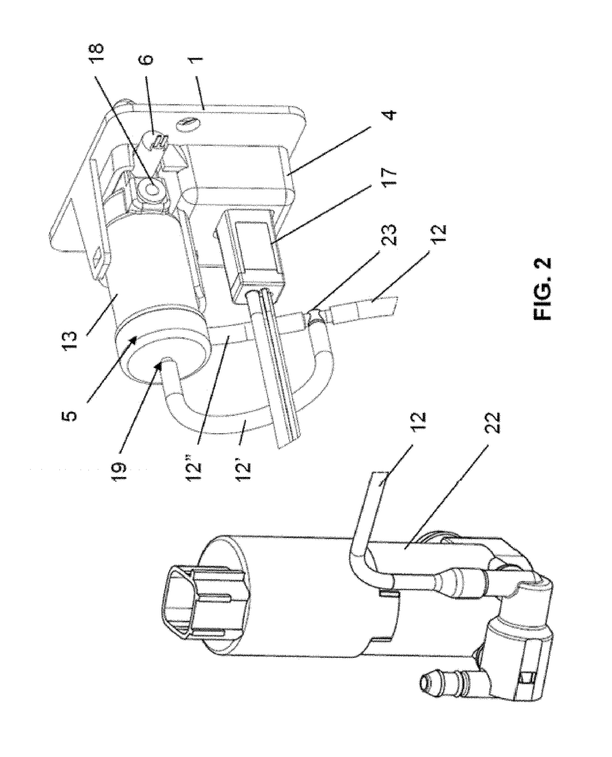
[0052]FIGS. 3 and 4 show the air pump 5 having a body 13 and an air-fluid interface housed inside the body. In this example, the body 13 is a cylinder having a fluid inlet 19 and an air outlet 21 and the air-fluid interface is a displaceable plunger 14. The plunger 14 splits the cylinder 13 into first and second portions such that a compression chamber 10 is defined by the first portion of the cylinder 13 and the plunger 14 and a fluid chamber 11 is defined by the second portion of the cylinder 13 and the plunger 14. A spring coil 15 is housed within the first portion of the cylinder 13 such that the plunger 14 is biased by the spring coil 15 towards the fluid inlet 19.

[0053]Alternatively, the spring coil 15 may be housed within the second portion of the cylinder 13 and arranged so as to bias the plunger 14 towards the fluid inlet opening 19.

[0054]The spring coil 15 is arranged to enlarge the volume of the compression chamber 10 after the air pump 5 has dispensed a blast of air. A o...

second embodiment

[0061]FIGS. 5 and 6 show the air pump 5 where the air-fluid interface is an elastic element 16 instead of a plunger 14. Specifically, the elastic element 16 in this embodiment is an elastic membrane. The elastic membrane 16 is attached to the cylinder 13 and splits it into first and second portions such that the compression chamber 10 is defined by the first portion of the cylinder 13 and the elastic membrane 16 and the fluid chamber 11 is defined by the second portion of the cylinder 13 and the elastic membrane 16.

[0062]In FIG. 5, the air pump 5 is in a non-operative state, where the first and second electrovalves 6, 7 are closed and the liquid pump 22 is not supplying liquid to the cleaning system.

[0063]With both electrovalves 6, 7 closed and the liquid pump 22 activated to pump washing liquid from a washing liquid reservoir to the washing liquid conduit 12 generating a flow of washing liquid, the air pump 5 is filled with washing liquid, whose pressure is applied to the elastic m...

third embodiment

[0066]FIGS. 7 and 8 show the air pump 5 where the air-fluid interface is an elastic element 16 having a bellow-shaped portion 20. The elastic element 16 is attached to the cylinder 13 and splits it into first and second portions such that the compression chamber 10 is defined by the first portion of the cylinder 13 and the elastic element 16 and the fluid chamber 11 is defined by the second portion of the cylinder 13 and the elastic element 16.

[0067]In FIG. 7, the air pump 5 is in a non-operative state, where the first and second electrovalves 6, 7 are closed and the liquid pump 22 is not supplying liquid to the cleaning system. In this state, the bellow-shaped portion 20 of the elastic element 16 is in a relaxed state.

[0068]With both electrovalves 6, 7 closed and the liquid pump 22 activated to pump washing liquid from a washing liquid reservoir to the washing liquid conduit 12 generating a flow of washing liquid, the air pump 5 is filled with washing liquid, whose pressure is appl...


PUM


Abstract

An aspect of the invention refers to a system for cleaning an external vehicle-mounted sensor surface. The system comprises an air nozzle arranged to discharge air onto a sensor surface; an air pump comprising a fluid inlet, an air outlet, an air-fluid interface and a variable volume compression chamber communicated with the air outlet; an air flow control device communicated with the air nozzle and the air outlet for controlling the flow of air therethrough; and a liquid pump communicated with the fluid inlet to supply a flow of pressurized liquid such that the volume of the compression chamber varies to generate a volume of pressurized air with an absolute pressure below 10 bar.

Description

CROSS-REFERENCES TO RELATED APPLICATIONS[0001]This patent application is a continuation-in-part of U.S. patent application Ser. No. 14 / 721,331, filed May 26, 2015, which claims priority to European Application No. 14382188.2, filed May 27, 2014. This patent application also claims priority to PCT Application No. PCT / EP2015 / 076546, filed Nov. 13, 2015. All of the aforementioned patent applications are incorporated herein by reference in their entirety.BACKGROUND OF THE INVENTION[0002]The present invention refers in general to techniques for automatically cleaning a surface of a sensor mounted on a vehicle by blowing air to remove light dirt (e.g. dust) from the surface or remove liquid drops on the surface (e.g. due to rain or washing) such that a clear signal can be captured anytime.[0003]More in particular, it is an object of the present invention to provide a system for automatically cleaning a sensor surface which, in a simple manner and with a reduced cost, is capable of complet...

Claims


Application Information

Patent Timeline
Patent Type & Authority Applications(United States)
IPC IPC(8): B60S1/56B60S1/54B60S1/48B08B7/04B08B5/02G02B27/00B08B3/02
CPCB60S1/56B60S1/481B60S1/54G02B27/0006B08B5/02B08B7/04B08B3/02B60S1/52F04B9/107F04B13/02F04B45/02F04B45/053F04B43/00
Inventor GALERA, ROBERT LOPEZLOPEZ, MIGUEL MOTAPITARCH, CARLOS ESTELLERESPINOSA, JOSE MANUELHERNANDEZ, OLALLO ALCAIDEESTEVEZ, CRISTIAN RODRIGUEZ
Owner FICO TRANSPAR
Why Eureka
Try Eureka