Capacitive sensor, sensor sheet, and method for manufacturing capacitive sensor

a capacitive sensor and sensor body technology, applied in the direction of instruments, pedestrian/occupant safety arrangements, force/torque/work measurement apparatus, etc., can solve the problems of poor flexibility, reduced flexibility in designing the sensor shape, disadvantageous presence of dead regions, etc., to improve the accuracy of detection of load distribution, increase flexibility in designing the cut shape of the sensor body in the cutting step, and high flexibility in wiring arrangement

Active Publication Date: 2017-11-02
SUMITOMO RIKO CO LTD
View PDF0 Cites 6 Cited by
  • Summary
  • Abstract
  • Description
  • Claims
  • Application Information

AI Technical Summary

Benefits of technology

[0007]The present invention was developed in view of the above circumstances, and it is an object of the present invention to provide a flexible, highly durable capacitive sensor and sensor sheet with high flexibility in designing wiring arrangement. It is also an object of the present invention to provide a method for manufacturing such a capacitive sensor.

Problems solved by technology

The presence of the dead region is therefore disadvantageous in the case where reduction in size and weight is required, such as in the case where the sensor is used in a limited space.
Moreover, since the manner in which the wiring layers are arranged is limited, flexibility in designing the sensor shape is reduced.
However, many of insulating layers used for printed circuit boards are made of an epoxy resin etc. and are therefore poor in flexibility.
Therefore, if such a three-dimensional wiring structure having an insulating layer that is poor in flexibility is used in the above capacitive sensor, extension and contraction of the electrode layers and the wiring layers are restricted by the insulating layer.
Moreover, the insulating layer may delaminate or fracture by repeated extension and contraction, which significantly increase electrical resistance when the insulating layer is extended.

Method used


Image

  • Capacitive sensor, sensor sheet, and method for manufacturing capacitive sensor
  • Capacitive sensor, sensor sheet, and method for manufacturing capacitive sensor
  • Capacitive sensor, sensor sheet, and method for manufacturing capacitive sensor

Examples


first embodiment

[0055]

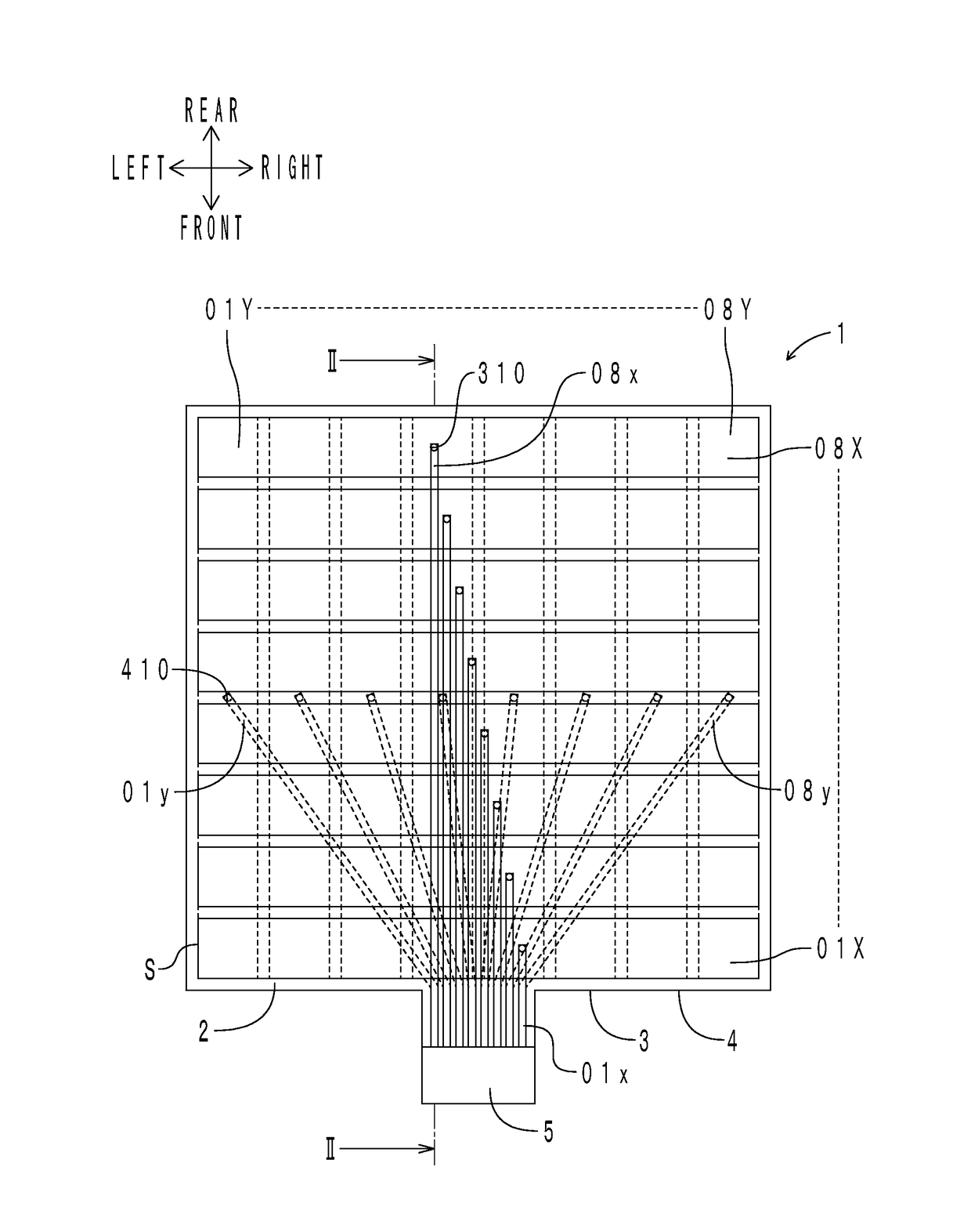
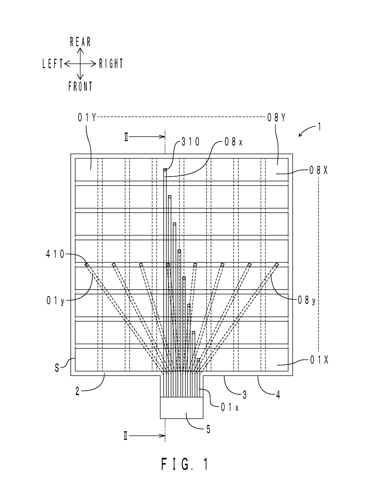
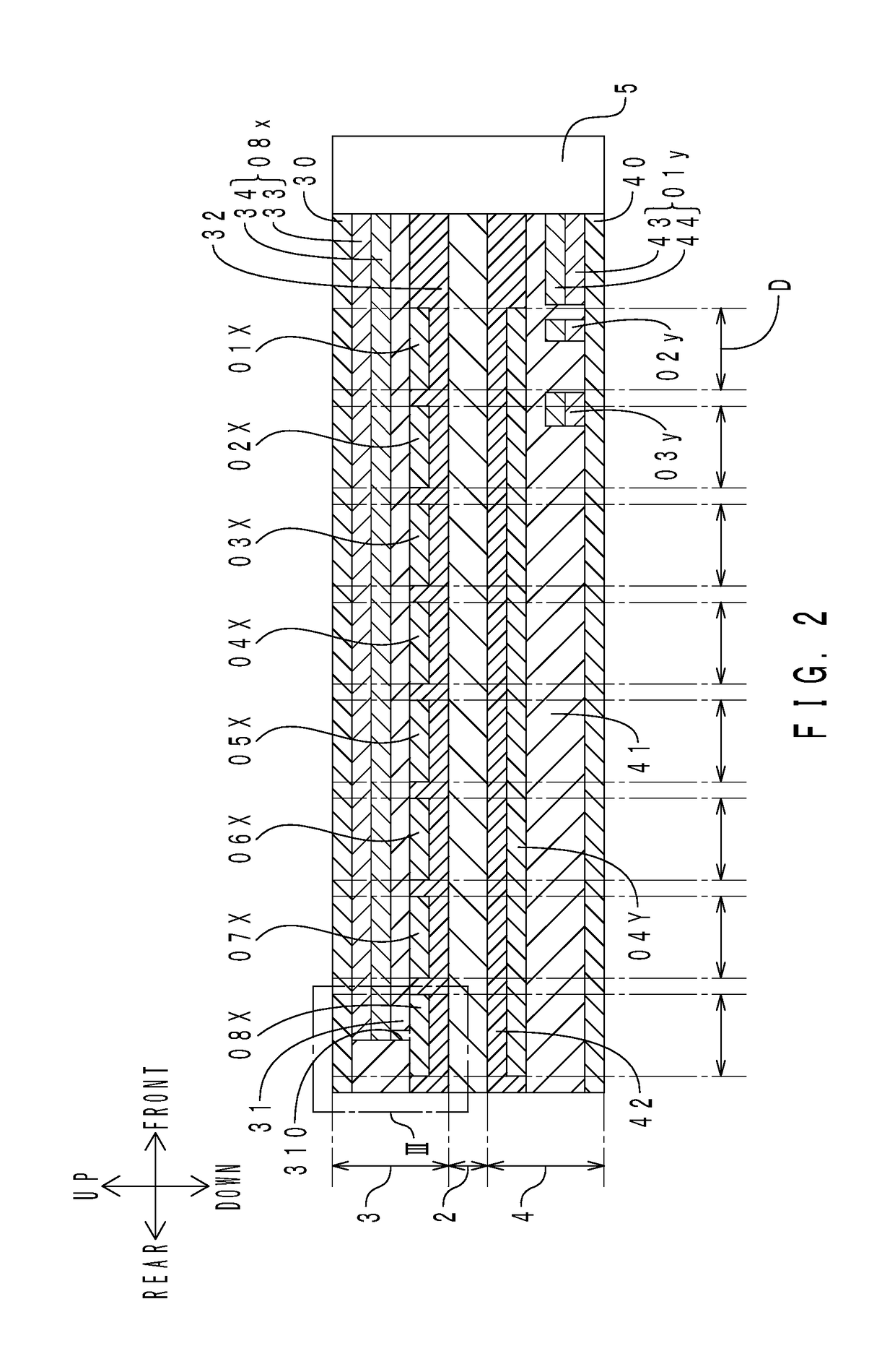
[0056]First, the configuration of a capacitive sensor of the present embodiment will be described. FIG. 1 is a transparent top view of the capacitive sensor of the present embodiment. FIG. 2 is a sectional view taken along line II-II in FIG. 1. FIG. 3 is an enlarged view of an area III in FIG. 2. In FIG. 1, a back-side electrode unit is shown by dotted lines.

[0057]As shown in FIGS. 1 to 3, a capacitive sensor 1 includes a dielectric layer 2, a front-side electrode unit 3, a back-side electrode unit 4, and a connector 5.

[0058]The dielectric layer 2 is made of urethane foam and is in the form of a square sheet. The thickness of the dielectric layer 2 is 300 μm. The front-side electrode unit 3 is located on the upper side of the dielectric layer 2, and the back-side electrode unit 4 is located on the lower side of the dielectric layer 2.

[0059]The front-side electrode unit 3 has a front-side substrate 30, eight front-side jumper wiring layers 01x to 08x, a front-side insulating la...

second embodiment

[0110]The configuration of a sensor sheet of the present embodiment is different from that of the capacitive sensor of the first embodiment in the number of front-side electrode layers and back-side electrode layers, the number of detection units, the number of front-side jumper wiring layers and back-side jumper wiring layers, and the wiring patterns of the front-side jumper wiring layers and the back-side jumper wiring layers, etc. A method for manufacturing the sensor sheet of the present embodiment is similar to the method for manufacturing the capacitive sensor of the first embodiment. A method for manufacturing a capacitive sensor of the present embodiment is different from the method for manufacturing the capacitive sensor of the first embodiment in that the method for manufacturing the capacitive sensor of the present embodiment has a cutting step. The differences in configuration from the first embodiment will be mainly described below.

[0111]

[0112]First, the configuration o...

third embodiment

[0151]A sensor sheet of the present embodiment is different from the sensor sheet of the second embodiment in that front-side contacts and back-side contacts are individually placed in all detection units. Only the differences from the second embodiment will be described below.

[0152]FIG. 11 is a transparent top view of the sensor sheet of the present embodiment. In FIG. 11, portions corresponding to those in FIG. 6 are denoted with the same reference characters as those in FIG. 6. Front-side electrode layers 1X to 3X and front-side jumper wiring layers 1x to 3x are shown by solid lines, back-side electrode layers 1Y to 3Y and back-side jumper wiring layers 1y to 3y are shown by dotted lines, and front-side contacts and back-side contacts are shown by black dots.

[0153]As shown in FIG. 11, the front-side jumper wiring layer 1x includes a main line portion 1x0 and three branch line portions 1x1 to 1x3. The main line portion 1x0 has its one end electrically connected to a connector 5. T...


PUM


Abstract

Provided is a flexible, durable capacitive sensor that achieves high flexibility in designing wiring arrangement. A capacitive sensor includes a dielectric layer and a plurality of electrode units placed on both sides of the dielectric layer in the front-back direction. The electrode unit includes an insulating layer having through holes extending therethrough in the front-rear direction, electrode layers placed on one side of the insulating layer in the front-back direction, and jumper wiring layers placed on the other side of the insulating layer in the front-back direction and electrically connected to the electrode layers through the through holes. The insulating layer has an elongation at break of 60% or more, a tension set of less than 5%, and a volume resistivity of 1.0×10¹⁰ Ω·cm or more.

Description

INCORPORATION BY REFERENCE[0001]The disclosure of Japanese Patent Application No. 2015-152447 filed on Jul. 31, 2015 including the specification, drawings and abstract is incorporated herein by reference in its entirety.BACKGROUND OF THE INVENTION1. Field of the Invention[0002]The present invention relates to capacitive sensors that can detect a load based on a change in capacitance, sensor sheets, and methods for manufacturing a capacitive sensor.2. Description of Related Art[0003]For example, Japanese Patent Application Publication No. 2013-096716 (JP 2013-096716 A) discloses a capacitive sensor including a dielectric layer and a plurality of front-side electrode layers and a plurality of back-side electrode layers which are disposed with the dielectric layer interposed therebetween. FIG. 12 is a transparent top view of the capacitive sensor disclosed in JP 2013-096716 A. As shown in FIG. 12, a capacitive sensor 9 includes a dielectric layer 90, front-side electrode layers 01X to ...

Claims


Application Information

Patent Timeline
Patent Type & Authority Applications(United States)
IPC IPC(8): G01R27/26
CPCG01R27/2605G06F2203/04103B60R21/01532G01L1/146G01L5/0014G06F3/04164G06F3/0445G01D5/24G06F3/044G01L1/14G01L5/00
Inventor KAWAGUCHI, JUNYAFUJIKAWA, TOMOHIROTAGUCHI, YUTAROYAMADA, HIROSHI
Owner SUMITOMO RIKO CO LTD
Why Eureka
Try Eureka