Adaptive Repair Method for Aerofoil Blades

a technology for aerofoil blades and adaptable repair methods, applied in the field of repair/maintenance of aero engine components, can solve the problems of inability to consider what to do in an area where there is no prior art method, slow repair methods, and high cost, and achieve the effect of improving speed and processing tim

Active Publication Date: 2017-11-02
ROLLS ROYCE PLC
View PDF2 Cites 8 Cited by
  • Summary
  • Abstract
  • Description
  • Claims
  • Application Information

AI Technical Summary

Benefits of technology

[0028]In contrast to known techniques, the model is “stitched” to measured stub. Actual deposited material (not measured and nominal points) are used for both the material addition part and the re-profiling, providing advantages in speed and processing time.

Problems solved by technology

Furthermore, each bladed disk component that is a candidate for repair will have experienced idiosyncratic in-service operating conditions and respective damage.
Whilst these repair methods do work they are slow, expensive and are highly dependent on the skill of the craftsmen involved.
However, prior art methods do not consider what to do in an area where there is no measurement data, for example in a repair process where the component is damaged and material is missing.
In addition, the build and type of certain engines mean that their blades or bladed disks require a full chord repair, rebuilding a full aerofoil from material addition before re-profiling.

Method used


Image

  • Adaptive Repair Method for Aerofoil Blades
  • Adaptive Repair Method for Aerofoil Blades
  • Adaptive Repair Method for Aerofoil Blades

Examples


Embodiment Construction

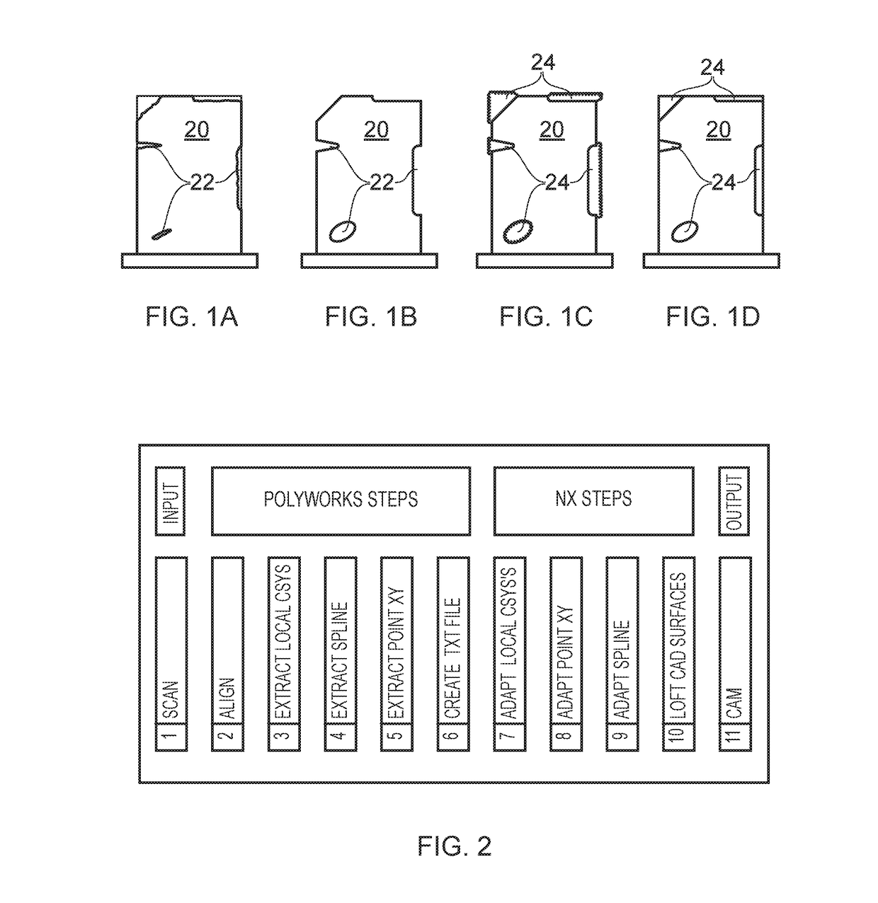
[0041]FIGS. 1A to 1D illustrate the steps of a typical repair process on a component 20. At each stage of the process highly skilled labour is required to perform each task to the required standards for aero engine repairs.

[0042]The first step, shown in FIG. 1A, is sentencing. This requires a skilled inspector to identify and classify the damaged area(s) 22 of the component 20. The component 20 is the cleaned, as illustrated in FIG. 1B, to prepare the damaged area(s) 22 for material addition. FIG. 1C shows the result of the material addition step, the process of filling in the damaged area(s) 22, which is usually accomplished with welding 24 by a highly skilled welder. Finally, the result of dressing back the weld(s) 24 to restore the aerofoil surface, re-profiling, is illustrated in FIG. 1D. Again, this step requires a high level of skill.

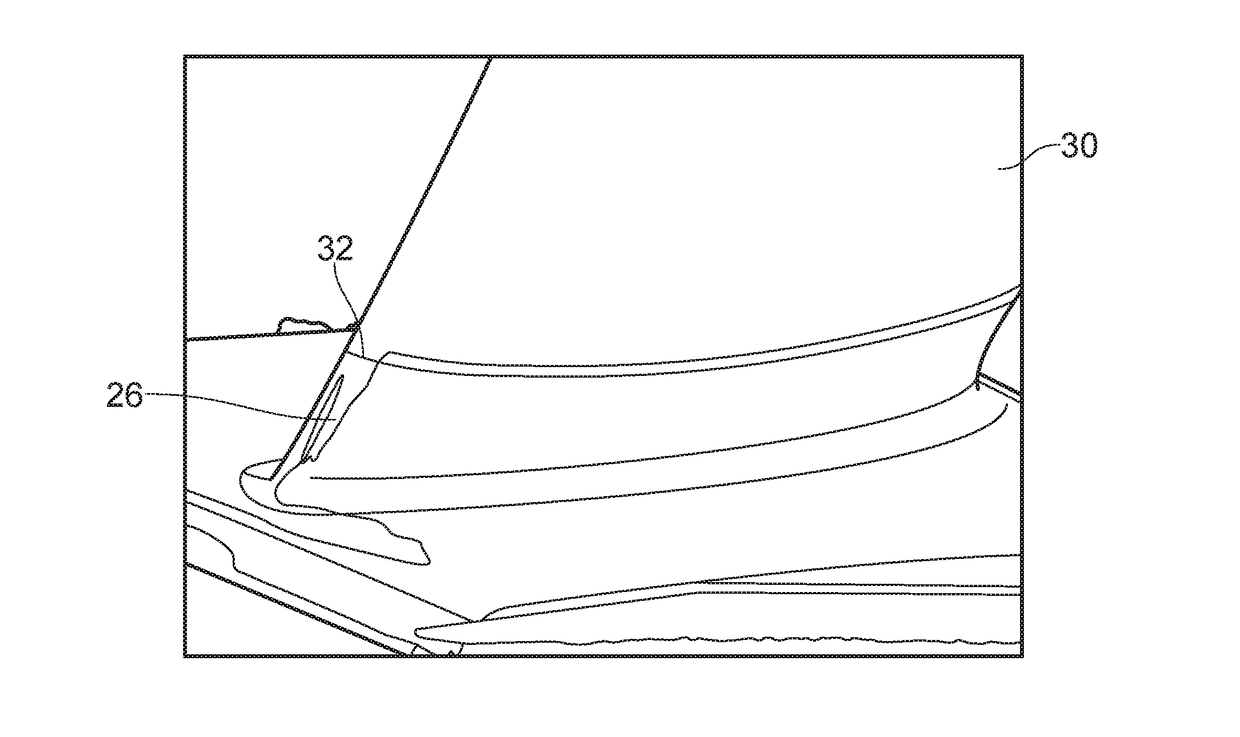
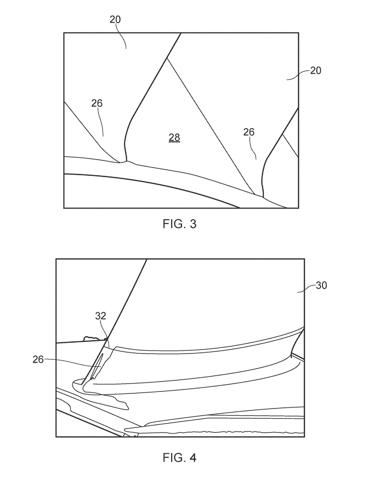
[0043]FIG. 2 sets out the process steps of the present disclosure in their most basic form. The steps apply for both material addition (MA) and r...


PUM

PropertyMeasurementUnit
sizeaaaaaaaaaa
shapeaaaaaaaaaa
areaaaaaaaaaaa

Abstract

This disclosure concerns an adaptive repair method, for example for aerofoil blade components. The method generates a digitised model of a physical component and uses data from the digitised model to align a part of the physical component with a nominal CAD model of the component. A combination of the digitised data and data from the nominal CAD model are then used to create an adapted model for repair of the component.

Description

CROSS-REFERENCE TO RELATED APPLICATIONS[0001]This application is based upon and claims the benefit of priority from British Patent Application Number 1607462.7 filed 29 Apr. 2016, the entire contents of which are incorporated by reference.BACKGROUND1. Field of the Disclosure[0002]The present disclosure relates to the repair / maintenance of aero engine components. More particularly, the disclosure relates to the ‘in-service’ repair of aerofoils for compressor blades and bladed disks.2. Description of the Related Art[0003]It is known that the original shape and profile of compressor aerofoils can change during routine in-service operation, and it is envisaged that this phenomenon may also affect compressor bladed disk aerofoils. Furthermore, each bladed disk component that is a candidate for repair will have experienced idiosyncratic in-service operating conditions and respective damage. Individual components will thus be unique in geometry and will require tailored measurement, materi...

Claims


Application Information

Patent Timeline
Patent Type & Authority Applications(United States)
IPC IPC(8): G06F17/50
CPCG06F17/5009G06F17/5086G05B19/401G05B2219/45147Y02P90/02B23P6/007G06F30/17G06F30/20
Inventor HUCKERBY, KARL S.
Owner ROLLS ROYCE PLC
Why Eureka
Try Eureka