Method and device for increasing the data transmission capacity in a serial bus system

a serial bus and data transmission technology, applied in data switching networks, instruments, coding, etc., can solve problems such as unsatisfactory results of related art, and achieve the effects of improving the reliability of data transmission or detection probability, reducing bit length, and reducing bit length

Active Publication Date: 2017-03-14
ROBERT BOSCH GMBH
View PDF70 Cites 5 Cited by
  • Summary
  • Abstract
  • Description
  • Claims
  • Application Information

AI Technical Summary

Benefits of technology

[0012]By providing a possibility for enlarging the data field of a transmitted message, the present invention achieves the effect that a greater quantity of data may be transmitted across the bus by a single message compared to a standard-conforming CAN in that, when a first switchover condition is satisfied, the data field of the messages may comprise more than eight bytes in deviation from the CAN standard ISO 11898-1, the values of the bits of the data length code being interpreted at least partially in deviation from the CAN standard ISO 11898-1 for determining the size of the data field when the first switchover condition is satisfied. This advantageously increases the ratio of data quantity and control information in a message and thus also the average data transmission rate over the bus system.
[0023]An additional advantage is that a standard CAN controller only needs to be modified minimally in order to be able to operate in accordance with the present invention. A communications controller according to the present invention, which is also able to work as a standard CAN controller, is only negligibly larger than a conventional standard CAN controller. The associated application program does not need to be modified, and even then advantages in the speed of data transmission are already achieved.

Problems solved by technology

It is clear that the related art does not provide results that are satisfactory in every respect.

Method used


Image

  • Method and device for increasing the data transmission capacity in a serial bus system
  • Method and device for increasing the data transmission capacity in a serial bus system
  • Method and device for increasing the data transmission capacity in a serial bus system

Examples


Embodiment Construction

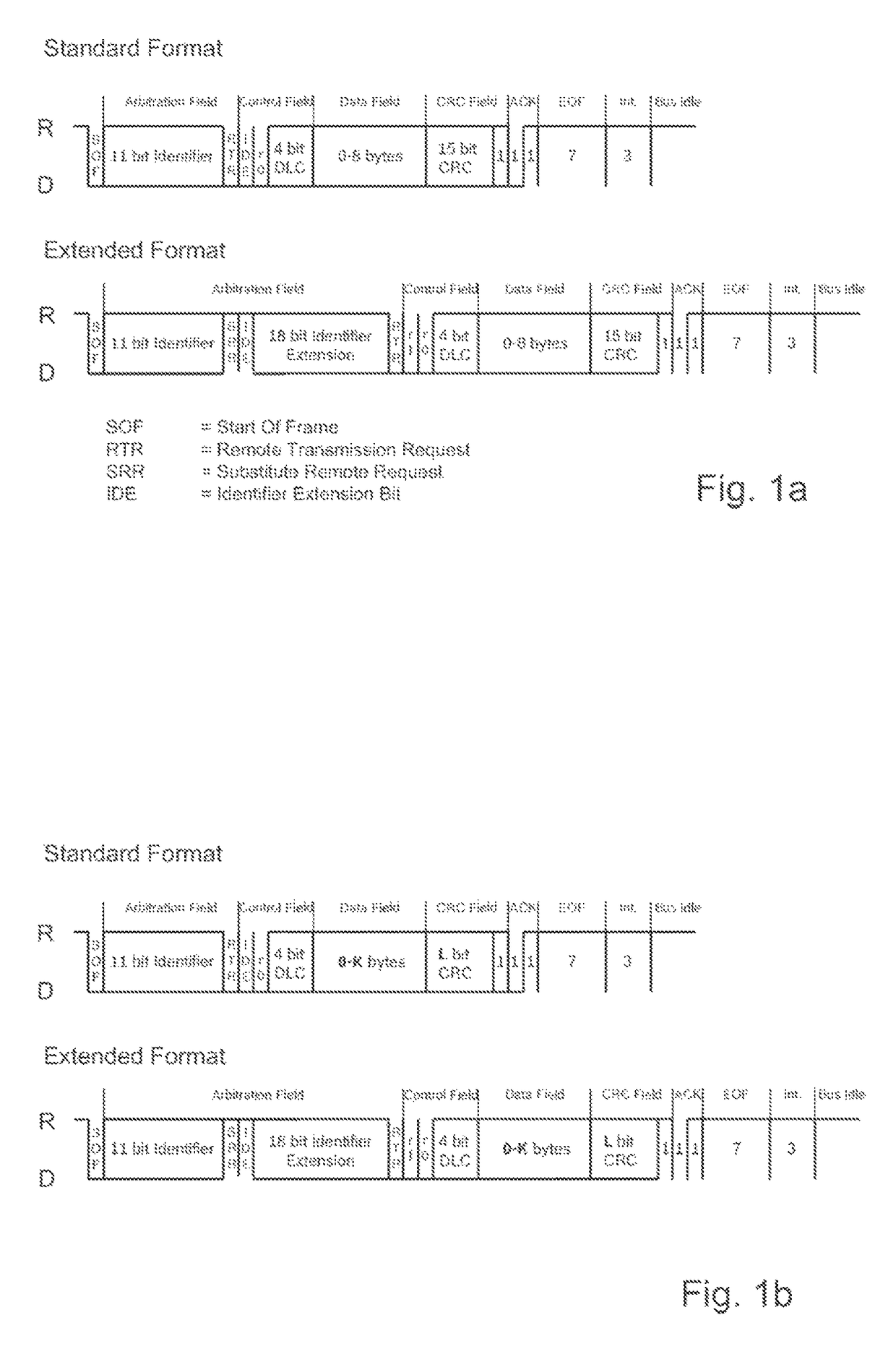
[0034]FIG. 1a shows the structure of messages as they are used in a CAN bus for data transmission. The two different formats “standard” and “extended” are shown. The method according to the present invention is equally applicable to both formats.

[0035]The message begins with a “start of frame” (SOF) bit, which signals the beginning of the message. This is followed by a section that is used primarily for identifying the message and on the basis of which the subscribers of the bus system decide whether they receive the message or not. This section is called an “arbitration field” and contains the identifier. This is followed by a “control field” containing, among other things, the data length code. The data length code contains information about the size of the data field of the message. This is followed by the actual “data field”, which contains the data to be exchanged between the subscribers of the bus system. This is followed by the “CRC field” having the 15-bit checksum and a del...


PUM


Abstract

A method is described for serial data transmission in a bus system having at least two subscribed data processing units that exchange messages via the bus, the transmitted messages having a logical structure in accordance with CAN standard ISO 11898-1, the logical structure including a start-of-frame bit, an arbitration field, a control field, a data field, a CRC field, an acknowledge field and an end-of-frame sequence, the control field including a data length code, which contains information regarding the length of the data field. When a first switchover condition is satisfied, the data field of the messages, in contrast to CAN standard ISO 11898-1, may comprise more than eight bytes, the values of the four bits of the data length code being interpreted at least partially in deviation from CAN standard ISO 11898-1 for determining the size of the data field when the first switchover condition is satisfied.

Description

CROSS REFERENCE TO RELATED APPLICATION[0001]The present application is the national stage entry of International Patent Application No. PCT / EP2012 / 055588, filed on Mar. 29, 2012, which claims priority to Application Nos. DE 10 2011 006 884.8, filed in the Federal Republic of Germany on Apr. 6, 2011, DE 10 2011 078 266.4, filed in the Federal Republic of Germany on Jun. 29, 2011, and DE 10 2011 080 476.5, filed in the Federal Republic of Germany on Aug. 5, 2011.FIELD OF INVENTION[0002]The present invention relates to a method and a device for increasing the data transmission capacity between at least two subscribers in a serial bus system.BACKGROUND INFORMATION[0003]For example, the ISO standard family 11898-1 through -5 describes the Controller Area Network (CAN) as well as an extension of the CAN called “time-triggered CAN” (TTCAN), referred to in the following also as standard CAN. The media access control method used in the CAN standard is based on a bit-wise arbitration. In bit-...

Claims


Application Information

Patent Timeline
Patent Type & Authority Patents(United States)
IPC IPC(8): H03M13/00H04L12/413G06F11/10G06F13/42H03M13/09H04L12/40H04L1/00
CPCG06F11/1004G06F13/4282H03M13/09H03M13/096H04L1/0083H04L12/4013H04L12/40169H04L12/413H04L1/0061H04L2001/0094H04L2012/40215G06F13/42
Inventor HARTWICH, FLORIAN
Owner ROBERT BOSCH GMBH
Why Eureka
Try Eureka