Antenna-in-package structures with broadside and end-fire radiations

a technology of broadside radiation and antenna, applied in the direction of resonant antennas, substantially flat resonant elements, instruments, etc., can solve the problems of low-cost device solutions required, low-cost rfic packages with integrated antennas, etc., to reduce surface waves, reduce surface waves, and reduce surface waves

Active Publication Date: 2017-11-02
IBM CORP
View PDF0 Cites 38 Cited by
  • Summary
  • Abstract
  • Description
  • Claims
  • Application Information

AI Technical Summary

Benefits of technology

[0006]In one embodiment of the invention, a package structure includes an antenna package and an RFIC (radio frequency integrated circuit) chip mounted to antenna package. The antenna package includes a stack structure, wherein stack structure includes a plurality of substrates and metallization layers comprising a first metallization layer formed on a first surface of a first substrate, and a second metallization layer formed on first surface of a second substrate. The first metallization layer includes a first planar antenna and a planar parasitic element disposed adjacent to the first planar antenna. The second metallization layer includes a second planar antenna. The RFIC chip is mounted to the second metallization layer of antenna package. The first antenna is connected to the RFIC chip by a first antenna feed line comprising a metalized via hole that is formed through the stack structure, and wherein the second antenna is connected to the RFIC chip by a second antenna feed line that is formed as part of the second metallization layer. The first planar antenna is configured to receive or transmit broadside signals and the second planar antenna is configured to receive or transmit end-fire signals. The planar parasitic element is configured to reduce surface waves on the surface of the first substrate.
[0007]In another embodiment of the invention, an antenna package includes a first substrate, a second substrate bonded to the first substrate using a first adhesive layer, and a third substrate bonded to the second substrate using a second adhesive layer. The first substrate includes a first metallization layer disposed on a surface of the first substrate, wherein the first metallization layer comprises a first planar antenna and an ungrounded planar parasitic element disposed adjacent to the first planar antenna. The first planar antenna is configured to receive or transmit broadside signals, and the ungrounded planar parasitic element is configured to reduce surface waves on the surface of the first substrate. The second substrate includes a second metallization layer disposed on a surface of the second substrate, wherein the second metallization layer comprises a dedicated power plane to distribute DC power supply voltage. The third substrate includes a third metallization layer formed on first surface of the third substrate and a fourth metallization layer formed on a second surface of the third substrate. The third metallization layer comprises a dedicated ground plane. The fourth metallization layer comprises a plurality of contact pads, one or more antenna feed lines, and a second planar antenna, wherein the second planar antenna is configured to transmit or receive end-fire signals. The antenna package further includes a plurality of metalized via holes formed through the first, second and third substrates to provide one or more a

Problems solved by technology

However, for the 60-GHz market to flourish, not only are low-cost device so

Method used


Image

  • Antenna-in-package structures with broadside and end-fire radiations
  • Antenna-in-package structures with broadside and end-fire radiations
  • Antenna-in-package structures with broadside and end-fire radiations

Examples


Embodiment Construction

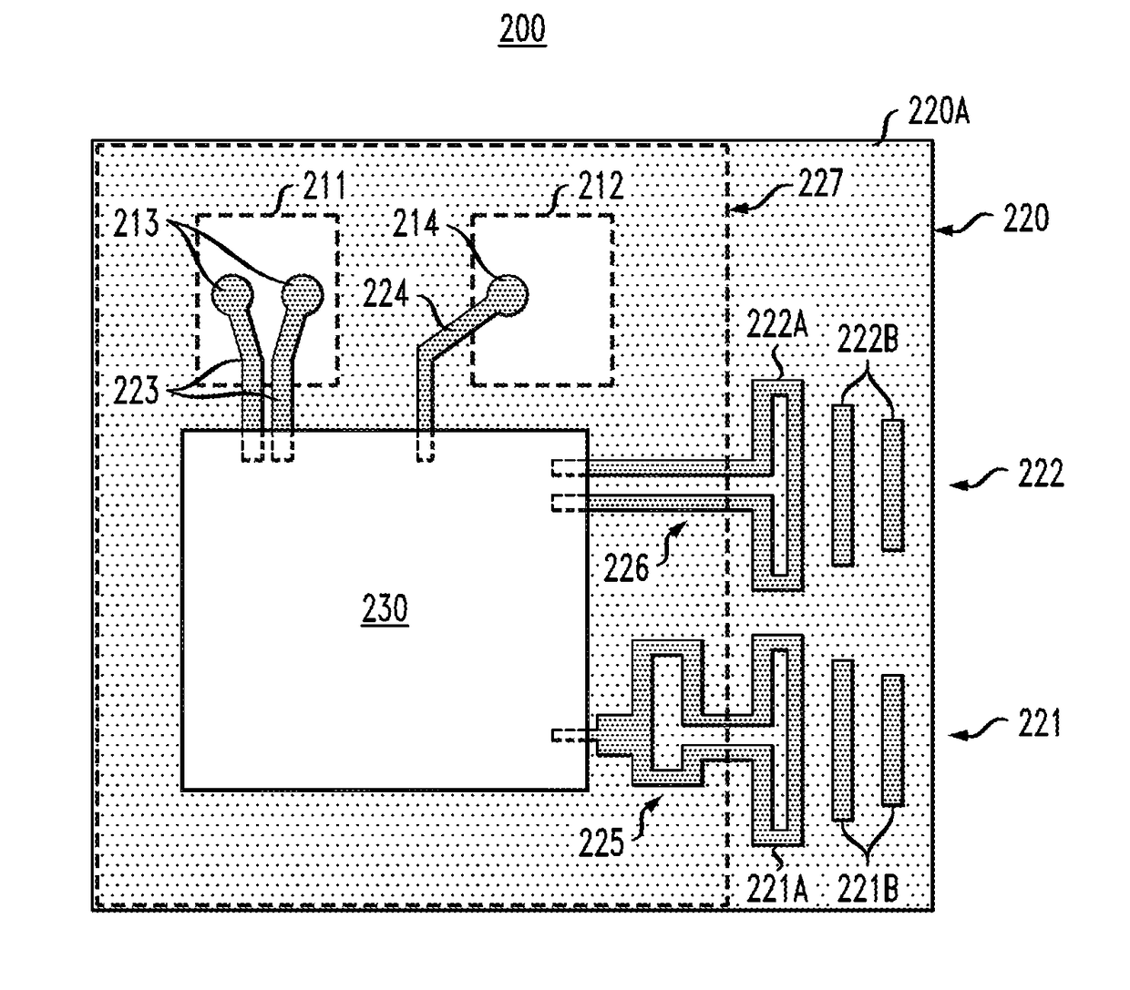
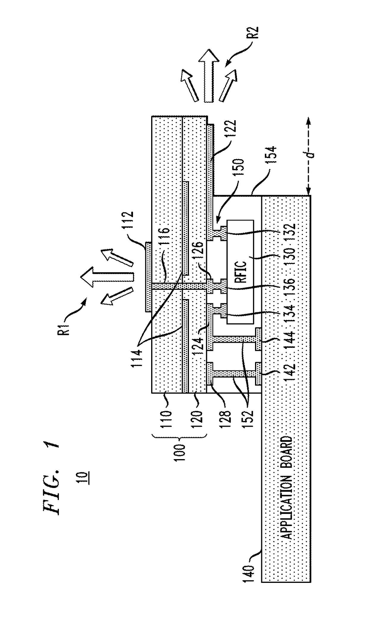
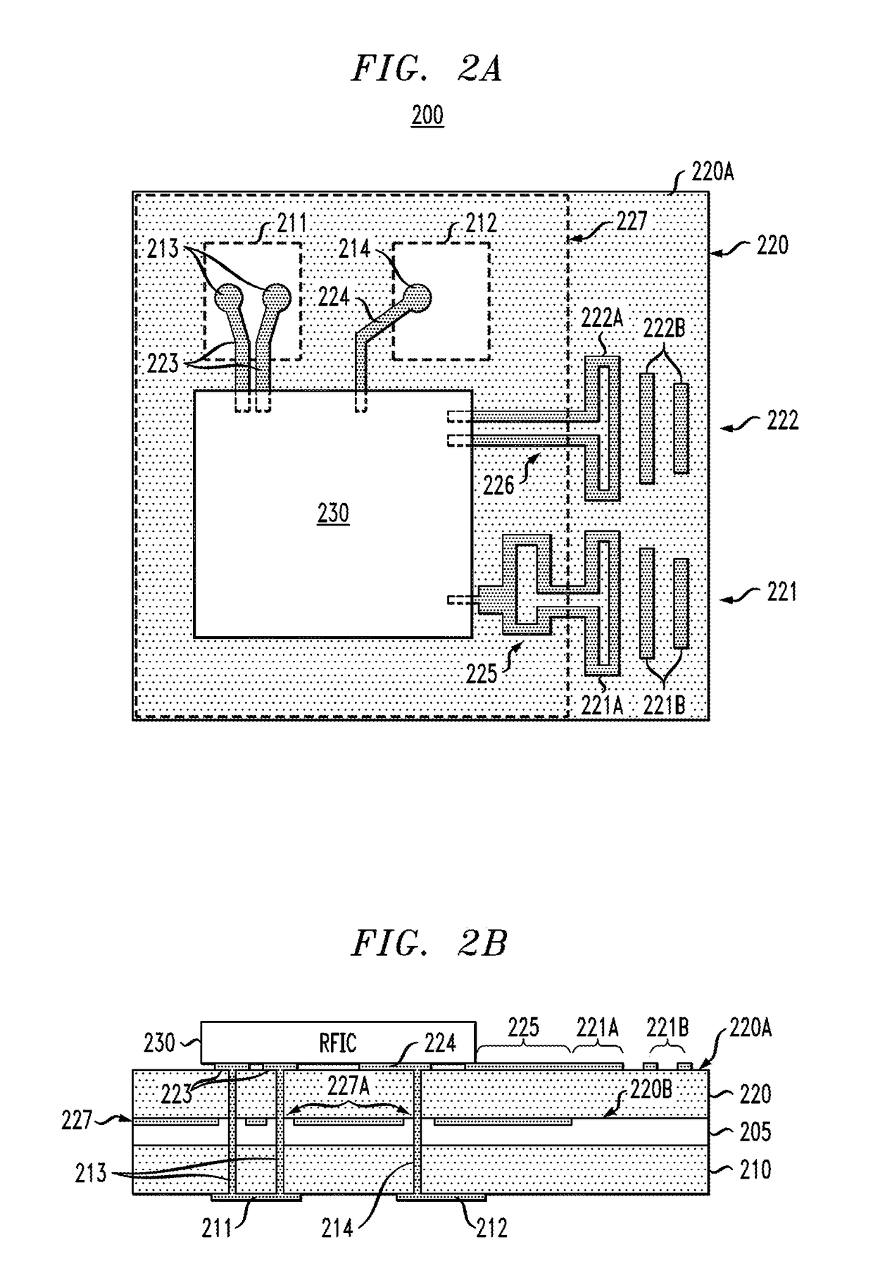
[0027]Embodiments of the invention will now be discussed in further detail with regard to structures and methods for integrally packaging antenna structures with semiconductor RFIC chips to form compact integrated radio / wireless communications systems that operate in the millimeter wave frequency range with radiation in broadside and end-fire directions. It is to be understood that the various layers, structures, and regions shown in the accompanying drawings are not drawn to scale, and that one or more layers, structures, and regions of a type commonly used in integrated antenna and chip packages may not be explicitly shown in a given drawing. This does not imply that the layers, structures and regions not explicitly shown are omitted from the actual integrated chip packages. Moreover, the same or similar reference numbers used throughout the drawings are used to denote the same or similar features, elements, or structures, and thus, a detailed explanation of the same or similar fe...


PUM


Abstract

Package structures are provided having antenna-in-packages that are integrated with semiconductor RFIC (radio frequency integrated circuit) chips to form compact integrated radio/wireless communications systems that operate in the millimeter wave (mmWave) frequency range with radiation in broadside and end-fire directions.

Description

CROSS-REFERENCE TO RELATED APPLICATIONS[0001]This application is a Continuation of U.S. patent application Ser. No. 14 / 565,616, filed on Dec. 10, 2014, which is a Continuation-in-Part of U.S. patent application Ser. No. 14 / 023,995, filed on Sep. 11, 2013, the disclosures of which are fully incorporated herein by reference.STATEMENT REGARDING FEDERALLY SPONSORED RESEARCH OR DEVELOPMENT[0002]This invention was made with Government support under Contract No. FA8650-09-C-7924 (awarded by the Advanced Research Development Agency). The Government has certain rights in this invention.TECHNICAL FIELD[0003]The field generally relates to package structures with integrated antennas and, in particular, package structures having antenna-in-packages integrated with semiconductor RFIC (radio frequency integrated circuit) chips to form compact integrated radio / wireless communications systems that operate in the millimeter wave (mmWave) frequency range with radiation in broadside and end-fire direct...

Claims


Application Information

Patent Timeline
IPC IPC(8): H01Q9/04G06K19/077H01Q19/30H01Q1/38H01Q23/00H01Q21/28H01L23/00
CPCH01Q9/0407H01L2224/16225G06K19/07749G06K19/077H01Q1/38H01Q19/30H01Q23/00H01L2224/32013H01L2924/15322H01L2924/15321H01L2224/73253H01L2224/73204H01L2224/33181H01L2224/32225H01L2224/32014H01L2224/16227H01L24/33H01L24/32H01L24/17H01L24/16H01L24/13H01L2224/17517H01L2224/131H01Q21/28H01L2924/15192H01L2223/6677H01L2924/3025H01L23/66H01L2924/014H01L2924/00012H01L2924/00
Inventor GARCIA, ALBERTO V.GU, XIAOXIONGLIU, DUIXIAN
Owner IBM CORP
Why Eureka
Try Eureka