Double cuff tracheostomy device

a tracheostomy device and double cuff technology, applied in the direction of tracheal tubes, respirators, etc., can solve the problems of tracheostomy patients at risk of air leakage, tracheostomy patients develop subcutaneous emphysema, and become problematic, so as to prevent or reduce the potential for air leakage, the effect of preventing the neck hole from getting permanently larger

Inactive Publication Date: 2017-11-09
MAYO FOUND FOR MEDICAL EDUCATION & RES
View PDF4 Cites 0 Cited by
  • Summary
  • Abstract
  • Description
  • Claims
  • Application Information

AI Technical Summary

Benefits of technology

[0012]Particular embodiments of the subject matter described in this document can be implemented to realize one or more of the following advantages. In some implementations, by adding a second cuff to the tracheostomy tube device in the area of the neck opening, air leaks can be prevented and / or treated effectively without the need for up-sizing or keeping the inner cuff inflated. The second cuff can be inflated around the skin hole, and thus prevent or reduce the potential for an air leak around the skin hole. The second cuff can be inflated and deflated to varying degrees depending on the degree of air leak. Using a second cuff instead of a larger tracheotomy tube may prevent the neck hole from getting permanently larger, and may also result in less risk of skin necrosis. In addition, since the skin, subcutaneous tissue, and tracheal cartilage is not a smooth and round shape like the plastic tube of a tracheostomy tube, a second cuff will conform better and thus decrease the risk of air leak. Further, the additional second cuff may also help secure the tracheotomy tube in place, and decrease the risk of it accidentally falling out.

Problems solved by technology

Patients with tracheostomies are at risk of developing air leaks.
In addition about 1% of patients with tracheostomies develop subcutaneous emphysema which can also become problematic.
However, this hinders pulmonary rehabilitation and prevents the patient from being able to speak.
The other option requires upsizing the size of the tracheostomy tube which is not ideal and can result in not only a larger tracheotomy hole but also a risk of skin necrosis.
Lastly, in some scenarios air leaks can be severe enough to result in respiratory decline and become an emergency.

Method used


Image

  • Double cuff tracheostomy device
  • Double cuff tracheostomy device
  • Double cuff tracheostomy device

Examples


Embodiment Construction

[0022]This document provides devices and methods for performing tracheostomies. For example, this document provides devices and methods for performing tracheostomies using tracheostomy tube devices that include a cuff at the neck opening area that can prevent or reduce the potential for air leaks.

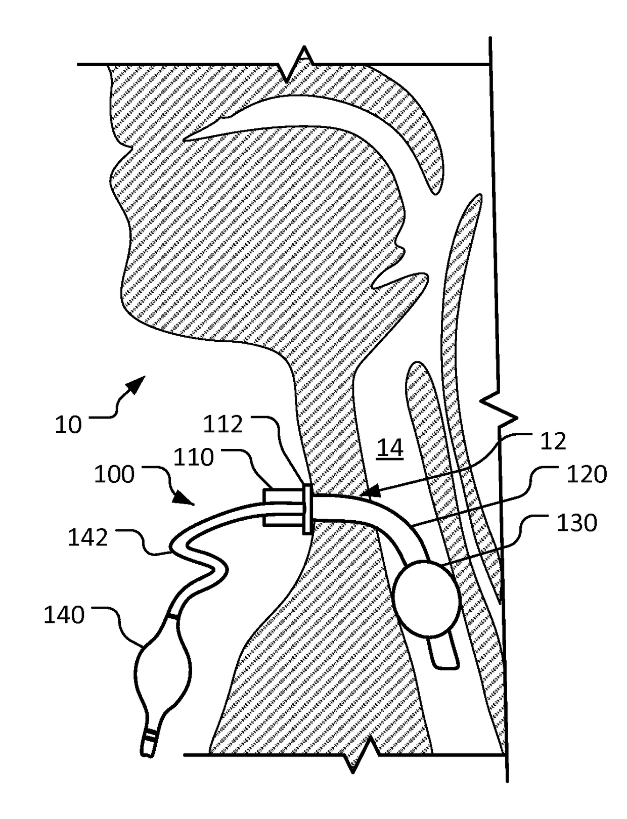
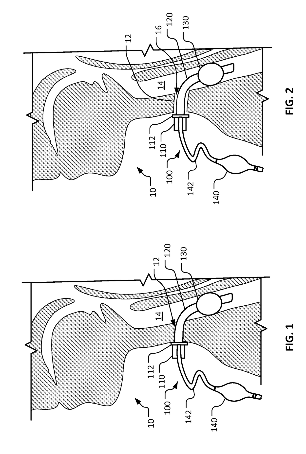
[0023]With reference to FIG. 1, a human patient 10 is being treated with a typical tracheostomy tube device 100. Patient 10 has a tracheostomy stoma 12 that provides surgical access to the patient's trachea 14 (airway).

[0024]Tracheostomy tube device 100 includes a proximal tube portion 110, a neck flange 112, a tube 120, a tracheal cuff 130, a pilot balloon 140, and a cuff inflation line 142. Proximal tube portion 110 is coupled to neck flange 112, and both are positioned external to patient 10. In some implementations, proximal tube portion 110 is a connector that can be used to attach a mechanical ventilator (not shown) to tracheostomy tube device 100. Tube 120 extends distally from neck ...


PUM


Abstract

This document provides devices and methods for performing tracheostomies. For example, this document provides devices and methods for performing tracheostomies using tracheostomy tubes that include a cuff at the neck opening area that can prevent or reduce the potential for air leaks.

Description

CROSS REFERENCE TO RELATED APPLICATIONS[0001]This application claims the benefit of U.S. Provisional Ser. No. 62 / 059,492 filed Oct. 3, 2014. This disclosure of the prior application is considered part of (and is incorporated by reference in) the disclosure of this application.BACKGROUND1. Technical Field[0002]This document relates to devices and methods for performing tracheostomies. For example, this document relates to devices and methods for performing tracheostomies using tracheostomy tube devices that include a cuff at the neck opening area that can prevent or reduce the potential for air leaks.2. Background Information[0003]Airway access for mechanical ventilation can be provided either by endotracheal or tracheostomy tube. In the acute setting an endotracheal tube is typically used, but tracheostomy tubes are often used for people who will require long-term use of a ventilator. A tracheotomy is a surgically created hole through the front of the neck and into the trachea. A tr...

Claims


Application Information

Patent Timeline
Patent Type & Authority Applications(United States)
IPC IPC(8): A61M16/04
CPCA61M16/0434A61M16/0402A61M16/044A61M16/0468A61M16/0465A61M16/0488A61M16/0459
Inventor AHO, JOHNATHON M.THIELS, CORNELIUS A.SPINDLER, BLAKE A.LUCAS, ALISHA A.
Owner MAYO FOUND FOR MEDICAL EDUCATION & RES
Why Eureka
Try Eureka