A sustainable lithographic printing plate
a lithographic printing plate and sustainable technology, applied in the field of sustainable lithographic printing plate, can solve the problems of pushed the limits of the current available state-of-the-art ctp system, time and energy consumption of each additional step, and achieve the effect of high press li
- Summary
- Abstract
- Description
- Claims
- Application Information
AI Technical Summary
Benefits of technology
Problems solved by technology
Method used
Image
Examples
example 1 and example 2
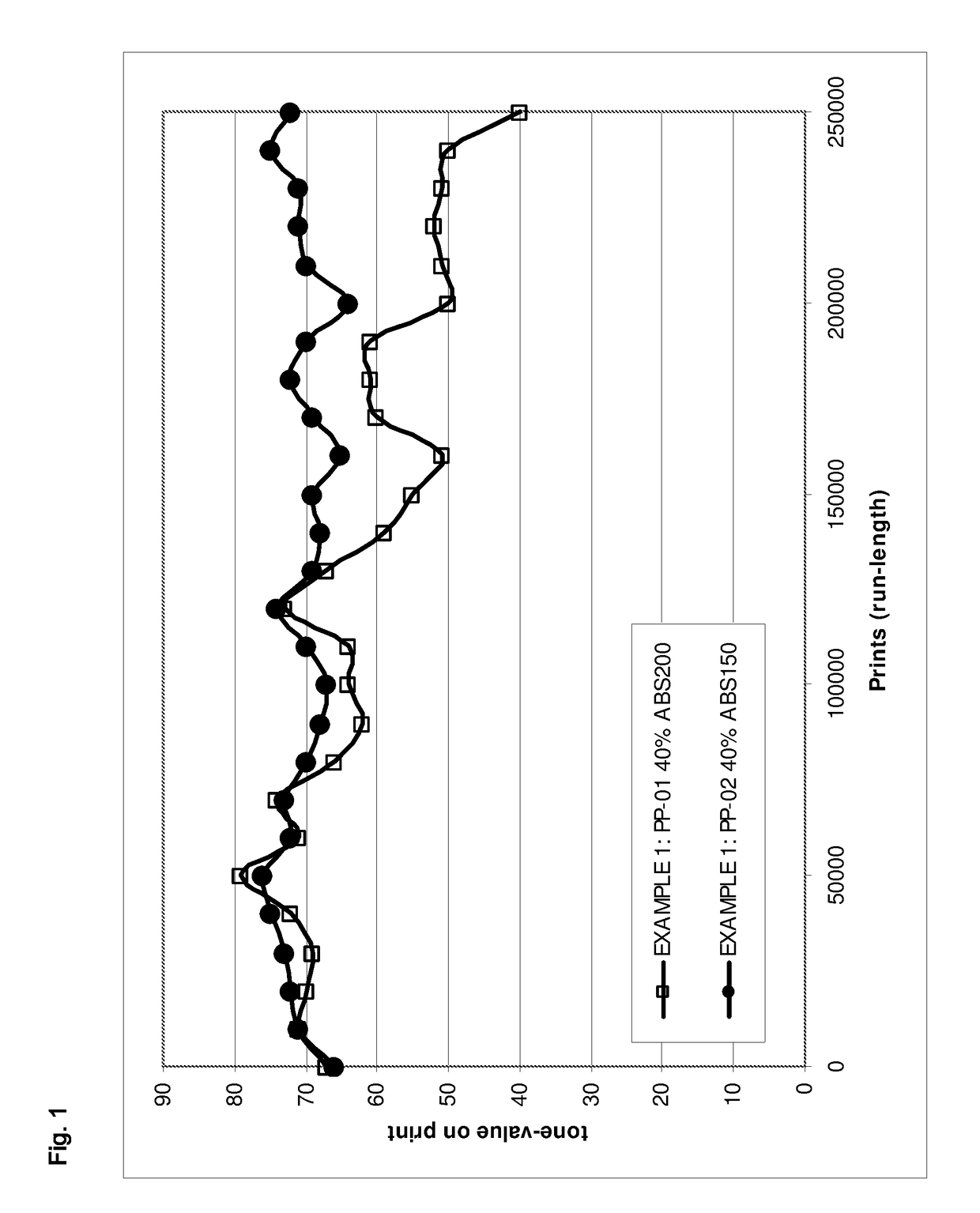
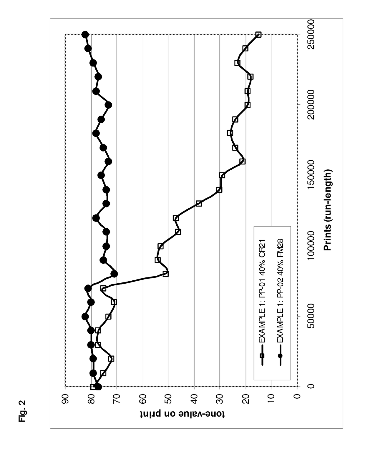
[0171]In the following two examples the chemical and mechanical resistance of the two lithographic printing plates (PP-01, PP-02) were evaluated. Print tests with both plates were carried out on a Drent™, an offset printing press, using newspaper stock 45 g / m2 paper and two different types of printing (OFFSETINK-01, OFFSETINK-02). The press-life of a lithographic printing plate is measured by the maximum run-length of prints where the print quality is acceptable.
[0172]The press-life of the two lithographic printing plates (PP-01, PP-02) were evaluated by measuring the tone-value of a raster image on print. The raster image was a result of halftoning a patch with tone-value of 40%. (PATCH40%_CR21, PATCH40%_ABS200, PATCH40%_FM28, PATCH40%_ABS150). The tone-value of these patches on print was measured with a Gretag optical densitometer D19C. The tone-value on print was compared to the Average Tone-value of prints 10000, 20000 and 30000 (AvTV). The print quality on print was evaluated a...
example 3
[0177]EXAMPLE 3 is the evaluation of the press-life, especially the abrasion, for the lithographic printing plate PP-01 and PP-02, carried out on a Drent™ and using OFFSETINK-02 as offset ink.
[0178]The SEM images in FIGS. 7 and 8 show an enlargement from a PATCH2×2 at the start and after 250000 prints with OFFSETINK-02 and PP-01 (FIG. 7) and PP-02 (FIG. 8). The dark squares, which are the ink-accepting dots, in the printing area of PATCH2×2 on PP-01 totally disappeared after 250000 prints while the rounded conical shape of the cured drops in the printing area of patch PATCH2×2 on PP-02 are still visible after 250000 prints.
example 4
[0179]In this example, the influence of the curing step on the thickness of the printing area of a printing plate prepared by the inkjet CTP system (IJCTP-01 is looked at.
a) Preparation a Lithographic Support
[0180]The lithographic support was similar prepared as in EXAMPLE 1.
b) Printing the Printing Areas
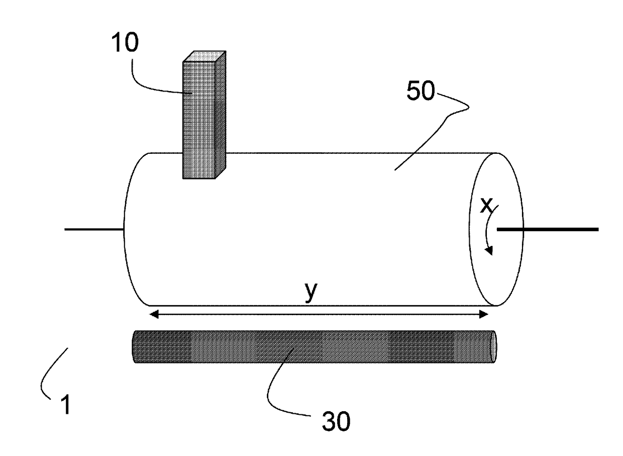
[0181]3 pL droplets were jetted with the inkjet CTP system IJCTP-01 on the lithographic support wherein the droplets were not touching each other on the lithographic support and then cured at different UV dose with UV LED-module (UV-01) to form cured single drops. Measuring the heights of the cured single drops is equivalent as measuring the thickness of a printing area. The heights of the cured droplets were measured with a Wyko NT3300 optical profiler. For these optical measurements an automated stage has been programmed to obtain a stitched area, build up by individual overlapping scans. Each scan has been measured with a 50× magnification and 0.5×FOV lens resulting in a field-of...
PUM
 Abstract
Description
Claims
Application Information
 - R&D
- Intellectual Property
- Life Sciences
- Materials
- Tech Scout
- Unparalleled Data Quality
- Higher Quality Content
- 60% Fewer Hallucinations
Browse by: Latest US Patents, China's latest patents, Technical Efficacy Thesaurus, Application Domain, Technology Topic, Popular Technical Reports.
© 2025 PatSnap. All rights reserved.Legal|Privacy policy|Modern Slavery Act Transparency Statement|Sitemap|About US| Contact US: help@patsnap.com


