Eureka AIR delivers breakthrough ideas for toughest innovation challenges, trusted by R&D personnel around the world.

Wave energy power generation device

A power generation device and wave energy technology, which is applied in the direction of ocean energy power generation, hydropower generation, engine components, etc., can solve the problems of reduced performance, low wave energy conversion efficiency, single power generation, etc., to achieve lubrication, improve work efficiency and use Performance, the effect of improving performance

Pending Publication Date: 2021-12-07
石宸宇
View PDF0 Cites 0 Cited by
  • Summary
  • Abstract
  • Description
  • Claims
  • Application Information

AI Technical Summary

Problems solved by technology

[0005] Aiming at the deficiencies of the prior art, the present invention provides a wave energy generating device, which solves the problem that the traditional wave energy generating device has too complicated structure, inconvenient use, low conversion efficiency of wave energy, and too single power generation, which cannot be fully utilized Wave energy affects power generation efficiency and reduces performance

Method used


Image

  • Wave energy power generation device
  • Wave energy power generation device
  • Wave energy power generation device

Examples


Embodiment example 1

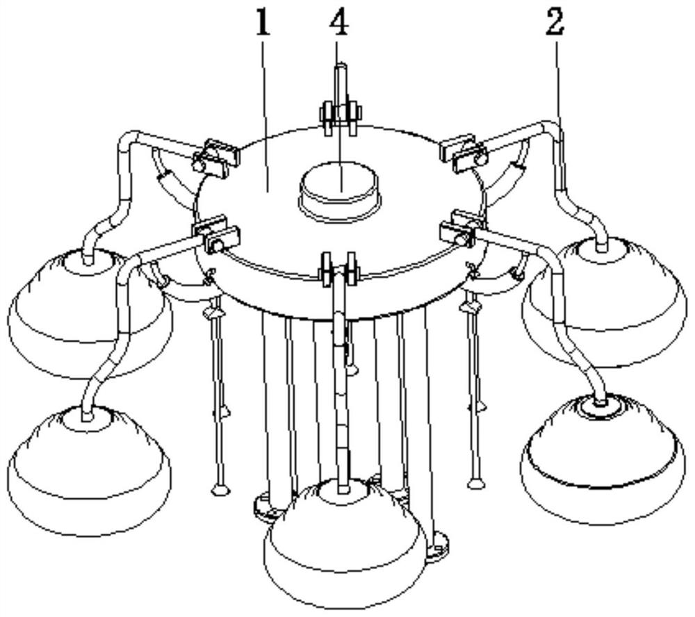
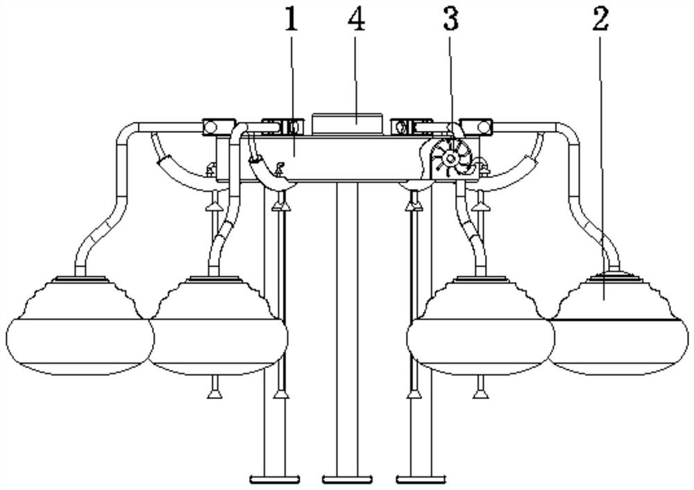
[0029] see Figure 1-6 , the present invention provides a technical solution: a wave energy power generation device, including a base body 1, a floating drive device 2, an impeller 3, and a first-stage power generation mechanism 4, the floating drive device 2 is arranged on the surface edge of the base body 1, and the impeller 3 is set Inside the base body 1 and close to the floating drive device 2, the first-stage power generation mechanism 4 is arranged at the top center of the base body 1;

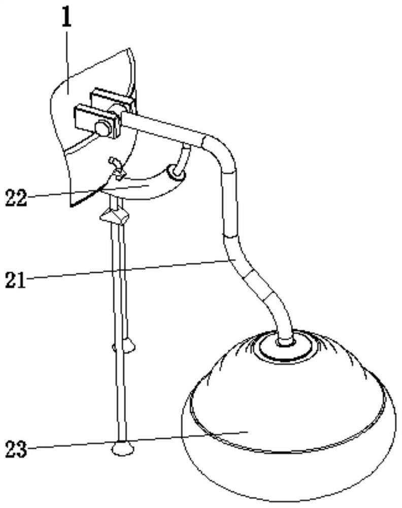
[0030] The floating driving device 2 is provided with a swing arm 21, a pressing device 22, and a float device 23. The top of the swing arm 21 is rotationally connected to the top edge of the base body 1, and the pressing device 22 is arranged on both sides corresponding to the surface of the swing arm 21 and the surface of the base body 1. In between, the buoy device 23 is arranged at the bottom of the swing arm 21 to quickly convert the wave energy and generate electricity in multiple...

Embodiment example 2

[0032] The pressing device 22 is provided with an arc-shaped cylinder 221 and an arc-shaped piston 222. One end of the arc-shaped cylinder 221 is fixed on the bottom of the substrate 1 and is located at the edge position. The arc-shaped piston 222 is connected with the arc-shaped cylinder 221. The arc-shaped piston 222 The top of the top is fixedly connected with the surface of the swing arm 21, and the liquid outlet end of the arc-shaped cylinder 221 extends to the inside of the base body 1 and is located at the position of the impeller 3. Under the influence of wave energy, the float device 23 floats up and down, and then through the swing arm 21 pair The arc-shaped piston 222 pulls and presses down, and controls the direction of the liquid in and out through the liquid inlet check valve 2201 and the liquid outlet check valve 2202 to absorb and drain the seawater, and the discharged high-pressure water is sprayed to the impeller 3, Make it rotate at a high speed, so that the ...

Embodiment example 3

[0034] Float device 23 is provided with pillar 231, float housing 232, arc rack 233, gear 234, secondary generator 235, oil injection device 236, rubber membrane 237, and pillar 231 is arranged on the inside of float housing 232 and the top and swing arm The bottom end of 21 is fixedly connected, and the bottom end of pillar 231 is rotationally connected with the bottom of the inner wall of float housing 232. One end of arc rack 233 is fixed at the bottom of the inner wall of float housing 232 and is connected with the pillar 231. The gear 234 is arranged on The inside of the pillar 231 is engaged with the arc-shaped rack 233, the secondary power generation mechanism 235 is arranged on the surface of the pillar 231 and connected with the gear 234, and the fuel injection device 236 is arranged at the end of the arc-shaped rack 233 Between the two sides corresponding to the bottom of the inner wall of the float housing 232, the rubber membrane 237 is arranged between the top of t...


PUM


Abstract

The invention discloses a wave energy power generation device. The device comprises a base body, a floating driving device, an impeller and a primary power generation mechanism, the floating driving device is arranged at the edge of the surface of the base body, the impeller is arranged in the base body and close to the floating driving device, and the floating driving device is provided with a swing arm, a pressing device and a floater device. The primary power generation mechanism is arranged in the center of the top of the base body, the top end of the swing arm is rotationally connected with the edge of the top of the base body, the pressing device is arranged between the two corresponding sides of the surface of the swing arm and the surface of the base body, and the floater device is arranged at the bottom end of the swing arm. The invention relates to the technical field of new energy power generation equipment. According to the wave energy power generation device, the purpose of multi-stage power generation is achieved, the structure is reasonable and simple, use is convenient, the wave energy conversion efficiency is high, power generation can be conducted at multiple positions at the same time, the wave energy is fully utilized, and the working efficiency and the use performance are improved.

Description

technical field [0001] The invention relates to the technical field of new energy power generation equipment, in particular to a wave energy power generation device. Background technique [0002] With the rapid development of science and technology, energy demand and energy shortage have become the subject of common concern. As conventional traditional energy sources such as coal, oil, natural gas, water energy, and wood, which are widely used by people, are decreasing with consumption, people urgently need New energy sources to replace these conventional energy sources. The ocean is rich in energy, which mainly includes wave energy, tidal energy, salt concentration, temperature difference, etc. Among them, wave energy is an inexhaustible and inexhaustible renewable energy source in the ocean. If it is effectively developed, it can benefit mankind. [0003] At present, the structure of the traditional wave energy power generation device is too complex, inconvenient to use,...

Claims


Application Information

Patent Timeline
Patent Type & Authority Applications(China)
IPC IPC(8): F03B13/18F03B11/02F03B11/00
CPCF03B13/1815F03B11/00F03B11/004F03B11/02Y02E10/30Y02E10/20
Inventor 石宸宇
Owner 石宸宇
Why Eureka
Eureka Blog
Learn More