Hard flooring plank and wall panel plank

a technology for wall panels and flooring, which is applied in the field of hard flooring plans and wall panel plans, can solve the problems of contaminating the construction site, affecting so as to reduce the difficulty and the laying cost, and ensure the laying effect. no contamination, and increase the laying efficiency of hard flooring plans

Inactive Publication Date: 2017-11-09
ZHEJIANG TIANZHEN BAMBOO & WOOD DEV
View PDF11 Cites 1 Cited by
  • Summary
  • Abstract
  • Description
  • Claims
  • Application Information

AI Technical Summary

Benefits of technology

[0006]A technical problem to be solved by the present invention is to provide a hard bonding flooring plank that can be assembled and disassembled quickly, which not only overcomes the disadvantages of an existing hard flooring plank, but also has the advantages of a soft flooring plank, so that a new breakthrough on the structure of the flooring plank is achieved.
[0024]Compared with the prior art, the present invention has the following beneficial effect. The foregoing technical solution is employed, that is the bottom surface of the flooring plank body is bonded with the retractable bonding element and the lower surface of the retractable bonding element is bonded with the release paper layer. Via this kind of structure, since the retractable bonding element has adherence and resilience, when the flooring plank is laid, the flooring of the present invention can be directly bonded to the ground. Thus, the hard flooring plank can have the advantages of the resilient flooring plank, thereby greatly increasing the laying efficiency of the hard flooring plank and reducing the laying difficulty and the laying cost of the hard flooring plank; moreover, the full coverage of the glue layer is not needed, no floor glue is needed to be coated and brushed on the construction site so that no contamination is caused. The flooring is very convenient to disassemble and replace. If any flooring in the middle is damaged and needs to be changed, the damaged flooring can be directly took off and replaced. The flooring is flexible and provides good foot feels when people walk thereon, without making any noises. The gaps between the flooring planks and the ground not only maintain the ventilation of air but also produce an air sound insulation effect between the flooring planks and the ground. Since the retractable bonding element has a retractable function, the retractable bonding element may be compressed to deform under the action of pressure and may rebound after the pressure is reduced or removed, thereby self adjusting the flatness and reducing the requirement on the flatness of the ground, which further reduces the use cost. Because the hard flooring plank of the prevent invention is bonded to the ground which is sufficient to prevent gaps between the hard flooring planks caused by displacement, the joint structures of the opposite side surfaces of the existing hard flooring plank are saved in this way, and overlapped structures at the lapped joints between the hard flooring planks are omitted, so that the processing cost of the hard flooring planks is further reduced, and the utilization rate of the hard flooring planks is improved. The release paper layer is provided to facilitate transferring and stacking the hard flooring planks, and the hard flooring planks can be bonded to any place by tearing off the release paper layer during use.
[0025]The present invention has further beneficial effects. Each retractable bonding element is as wide as the flooring plank body in the transverse direction of the flooring plank body. Such structure is more beneficial for increasing the stability of the flooring plank.
[0026]The present invention has further beneficial effects. Because the hard flooring plank of the prevent invention is bonded to the ground which is sufficient to prevent gaps between the hard flooring planks caused by displacement, it is possible to employ the micro-jointing structure with a size less than that of the existing joint structure. Employing the micro-jointing structure may further increase the whole connecting effect among various hard flooring planks and improve the whole flatness of the flooring. Although the micro-jointing structure is provided, the size thereof is smaller than that of the existing joint structure while being compared with the joint structure of the hard flooring plank in the prior art; moreover, the overlapped size at the lapped joint between the hard flooring planks is smaller, and the utilization rate of the hard flooring plank is increased; in addition, it is very convenient to clasp, so that the technical difficulty of installation is greatly decreased, and the processing and installation costs are greatly reduced. As an optimization, the micro-jointing structure is formed by the protruding edge arranged at one side of the flooring plank body and the groove arranged at the opposite side of the flooring plank body and matched with the protruding edge of the adjacent flooring plank body, and the protruding length of the protruding edge is greater than or equal to 0.1 mm and less than 3 mm. The micro-jointing structure with the protruding edge and the groove which are matched is also called as a micro tongue & groove (T&G) structure. Employing the micro T&G structure makes the structure of the wall panel plank simpler and is more convenient to joint and install in case of being sufficient to prevent gaps between the hard flooring planks caused by displacement, so that the technical difficulty of installation is further decreased, and the processing and installation costs are further reduced.
[0027]Compared with the prior art, the size of the micro T&G structure is smaller than that of the prior art, and the overlapped size at the lapped joint between the hard flooring planks is smaller; therefore, the utilization rate of the hard flooring plank is increased; in addition, since the micro T&G structure has a simple and smaller structure which is very convenient to install, the technical difficulty of installation is greatly decreased, and the processing and installation costs are greatly reduced. The effect is optimal when the protruding height of the protruding edge is greater than or equal to 0.5 mm and less than or equal to 2.9 mm.

Problems solved by technology

Both the resilient flooring planks and the hard flooring planks have advantages but also have tremendous disadvantages.
The resilient flooring plank has a low cost and is relatively simple for laying, but requires both good flatness of the ground and full coverage of a glue layer while being laid, which needs a high usage amount of glue and tremendously contaminates the construction site.
Moreover, the resilient flooring is inappropriate to disassemble and replace after the glue is solidified, and the resilient flooring has weak resilience and provides a hard foot feel when people walk thereon and also has a poor sound insulation effect.
However, when being laid, a keel needs to be assembled on the ground at first, then a subfloor is arranged on the keel, and finally, the hard flooring planks are laid on the subfloor, which needs more auxiliary materials, thus increasing the material cost, construction cost, and construction difficulty.
Furthermore, since the hard flooring planks are suspended above the ground, creaks are unavoidable over time when people walk on the flooring.
Particularly, since the joint structures of the hard flooring planks are still monopolized by foreign patents currently, the Chinese flooring enterprises producing these kinds of locks have to pay hundreds of millions of huge patent royalties every year, and these fees are finally borne by consumers, thus greatly increasing the cost of the flooring.

Method used


Image

  • Hard flooring plank and wall panel plank
  • Hard flooring plank and wall panel plank
  • Hard flooring plank and wall panel plank

Examples


Embodiment Construction

[0037]To make the technical solution of the present invention more clearly, the present invention will be described in details hereinafter with reference to FIGS. 1-9. It should be understood that the specific exemplary embodiments described in the description are merely for the purpose of explaining the present invention, but are not intended to limit the protection scope of the present invention.

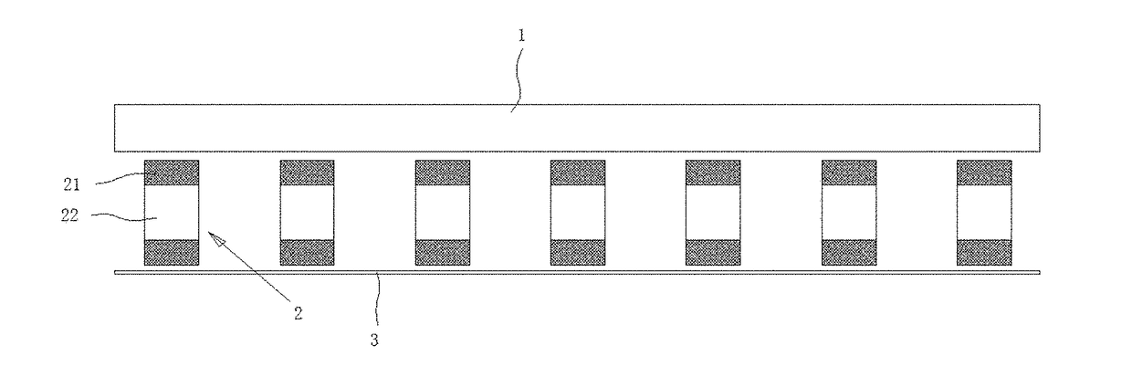
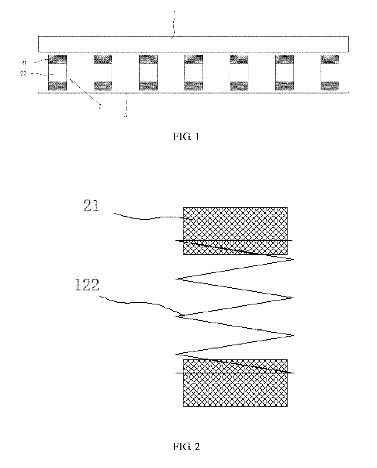
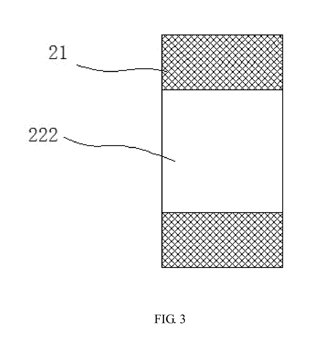
[0038]The present invention relates to a hard flooring plank including a flooring plank body 1, a bottom surface of the flooring plank body 1 is bonded with a retractable bonding element 2, and the retractable bonding element 2 may include a plurality of retractable bonding elements scattered on the bottom surface of the flooring plank body 1. Certainly, the plurality of retractable bonding elements 2 may also be uniformly distributed on the bottom surface of the flooring plank body 1. A lower surface of the retractable bonding element 2 is bonded with a release paper layer 3. The release ...


PUM

PropertyMeasurementUnit
lengthaaaaaaaaaa
lengthaaaaaaaaaa
protruding heightaaaaaaaaaa

Abstract

A hard flooring plank and a wall panel plank. The hard flooring plank includes a flooring plank body. A bottom surface of the flooring plank body is bonded with a retractable bonding element. A lower surface of the retractable bonding elements is bonded with a release paper layer. The wall panel plank includes a wall panel plank body. An inner side surface of the wall panel plank is bonded with a retractable bonding element, and the other side surface of the retractable bonding element is bonded with a release paper layer. The hard flooring plank not only overcomes the disadvantage of the hard flooring plank, but also has the advantages of a resilient flooring plank, so that a new breakthrough on the structure of the flooring plank body is achieved.

Description

BACKGROUND OF THE INVENTIONField of the Invention[0001]The present invention relates to a hard flooring plank and a wall panel plank.Description of the Related Art[0002]There are various types of flooring at present, including polyvinyl chloride (PVC) flooring, wood plastic flooring, PVC composite flooring, solid wood flooring, laminate flooring and so on. The flooring planks jointing these floorings are roughly in two types: one refers to flexible flooring planks, such as a thin PVC flooring plank and an artificial leather flooring plank, which are called as resilient flooring planks; and the other refers to anti-flexible flooring planks, such as a solid wood flooring plank, a thick PVC flooring plank and the like, which are called as hard flooring planks.[0003]The resilient flooring planks cannot be connected through joint structures (including a click lock and Tongue & Groove) arranged on side surfaces while being laid and are generally firmly bonded on a ground by brushing glue ...

Claims


Application Information

Patent Timeline
Patent Type & Authority Applications(United States)
IPC IPC(8): E04F15/02B32B7/12B32B21/04B32B21/08E04F13/08B32B3/06B32B27/08B32B25/08B32B27/30E04F15/04E04F15/10
CPCE04F15/0215E04F15/02038E04F13/0885B32B7/12B32B3/06B32B21/045B32B2307/51B32B25/08B32B27/08B32B27/304E04F15/04E04F15/10B32B2419/00B32B21/08B32B7/06B32B21/06B32B27/10B32B2260/026B32B2260/046B32B2307/732B32B2607/00E04F2201/0107E04F2290/044
Inventor FANG, QINGHUAWANG, YIBING
Owner ZHEJIANG TIANZHEN BAMBOO & WOOD DEV
Why Eureka
Try Eureka