Three-dimensional coordinate measurement apparatus

a measurement apparatus and three-dimensional coordinate technology, applied in measurement devices, error compensation/elimination, instruments, etc., can solve the problems of deteriorating measurement accuracy, less tolerance of fore-and-aft shaking, and affecting the accuracy of measurement, so as to improve the measurement accuracy of a position suppress the shaking of the y carriage, and improve the effect of measurement accuracy

Active Publication Date: 2017-11-09
TOKYO SEIMITSU
View PDF0 Cites 5 Cited by
  • Summary
  • Abstract
  • Description
  • Claims
  • Application Information

AI Technical Summary

Benefits of technology

[0040]According to the three-dimensional coordinate measurement apparatus of the present invention, measurement accuracy can be improved by suppressing shaking of the Y carriage.
[0041]In addition, according to the three-dimensional coordinate measurement apparatus of the present invention, it is possible to improve measurement accuracy of a position of the Y carriage in the Y-axis direction, that is, measurement accuracy of a Y coordinate value of the measuring object.
[0042]Further, according to the three-dimensional coordinate measurement apparatus of the present invention, deformation of the surface plate can be suppressed and measurement can be performed with high accuracy.

Problems solved by technology

However, the Y carriage is supported by a structure in which the surface plate is held in its entire lateral width by three air pads of the Y carriage in PTL 1, and thus the structure is tolerant of shaking in the side-to-side direction, but is less tolerant of shaking in the fore-and-aft direction.
Therefore, there is a problem in that shaking in a direction around the Z axis (yawing direction) is liable to occur.
In addition, since no air pad for reducing upward movement of the Y carriage is provided in PTL 1, shaking of the Y carriage in a direction around the X axis (pitching direction) may occur to deteriorate measurement accuracy.
Occurrence of shaking of the Y carriage in the pitching direction may deteriorate shaking in the yawing direction.

Method used


Image

  • Three-dimensional coordinate measurement apparatus
  • Three-dimensional coordinate measurement apparatus
  • Three-dimensional coordinate measurement apparatus

Examples


first embodiment

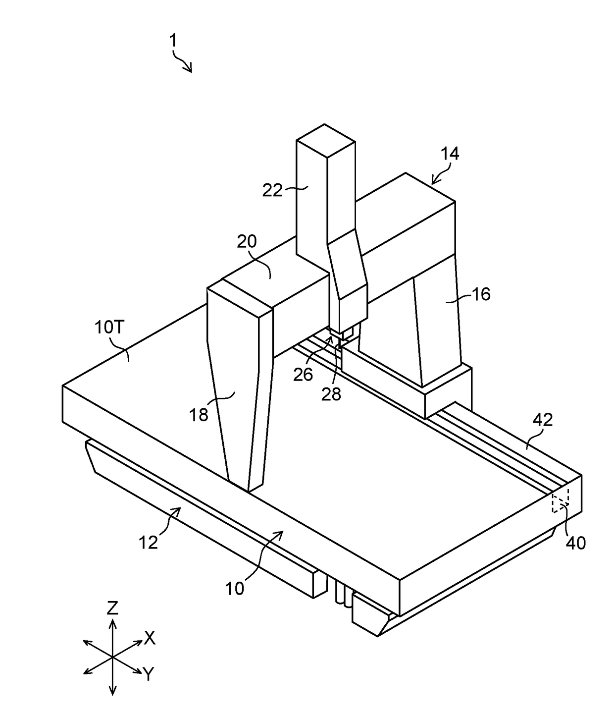
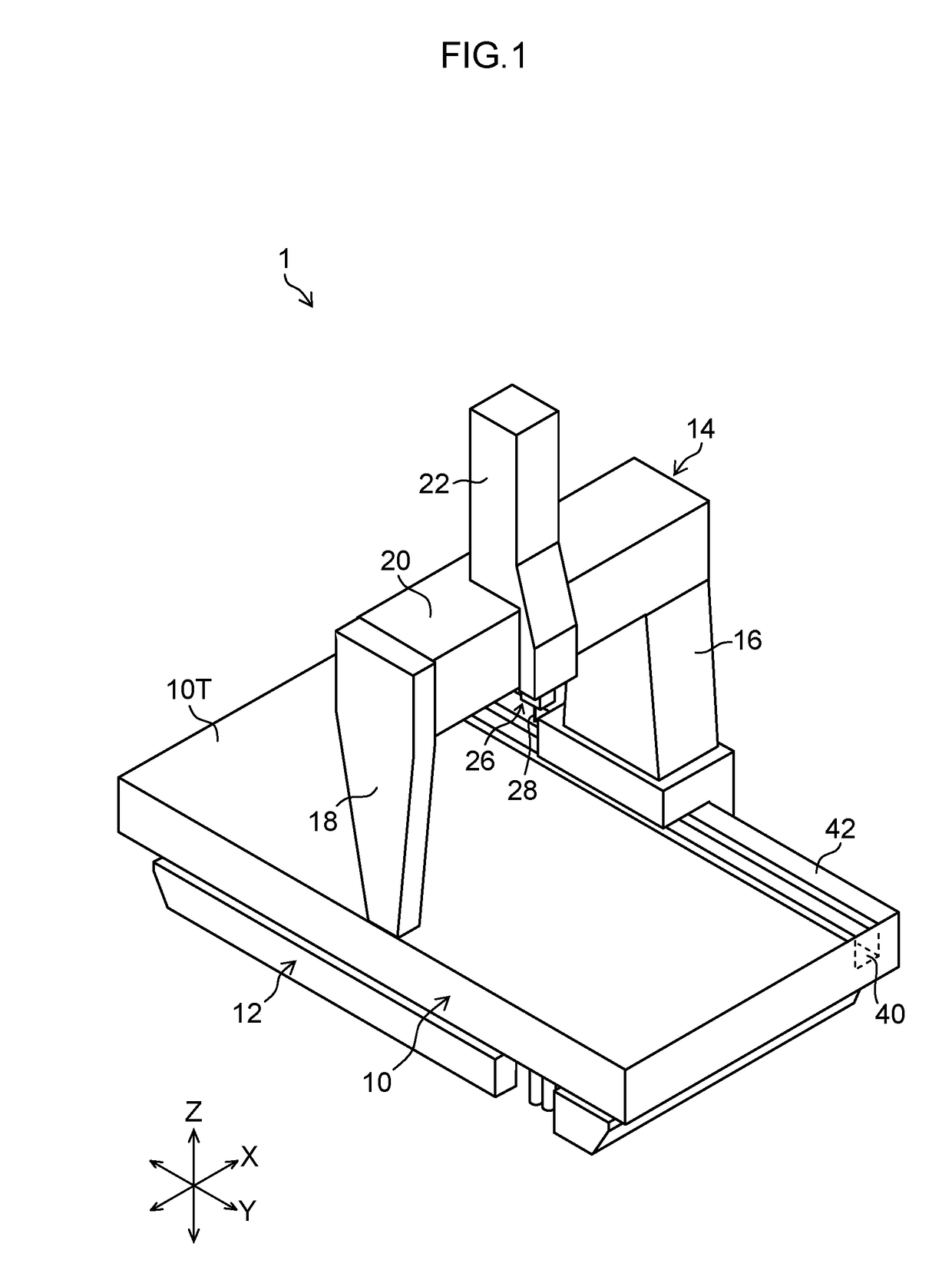
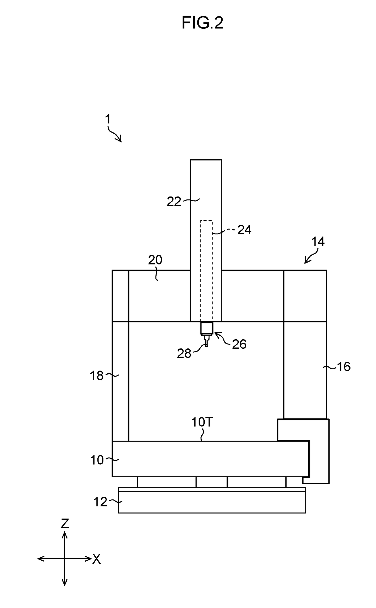
[0074]FIGS. 1 and 2 are respectively a perspective view and a front view each illustrating an appearance of a three-dimensional coordinate measurement apparatus 1 to which the present invention is applied (first embodiment).

[0075]The three-dimensional coordinate measurement apparatus 1 illustrated in FIGS. 1 and 2 includes a surface plate 10 supported by an installation face (floor face) through a mount base 12. The surface plate 10 is integrally formed of stone such as granite (Mikage) and marble (limestone, crystalline limestone) in a shape of a rectangle, and includes a flat top surface 10T on which a measuring object is placed. The top surface 10T is disposed parallel to an X-axis and a Y-axis, or perpendicular to a Z-axis. The surface plate 10 is not limited to a surface plate made of stone.

[0076]On the top surface 10T of the surface plate 10, a Y carriage 14 in a portal shape is provided across the surface plate 10. The Y carriage 14 includes a right Y carriage 16 being a firs...

second embodiment

[0194]In the three-dimensional coordinate measurement apparatus 1 according to the present embodiment, a covering member is provided in each of a front side surface 10F and a rear side surface 10E of the surface plate 10 in addition to the structure of the As illustrated in FIGS. 18, 19, and 20, plate-shaped thermal insulation members 150 and 152 are respectively fastened to the front side surface 10F and the rear side surface 10E of the surface plate 10, as covering members for covering substantially whole of the surfaces.

[0195]Accordingly, the amount of heat transferring from the front side surface 10F and the rear side surface 10E of the surface plate 10 to the inside of the surface plate 10 or to outside air is reduced. As a result, even if temperature (ambient temperature) of surrounding outside air of the surface plate 10 changes, temperature inside the surface plate 10 is less likely to change, whereby deformation of the surface plate 10 is reduced. In addition, as discussed...


PUM


Abstract

There is provided a three-dimensional coordinate measurement apparatus capable of reducing shaking of a Y carriage and improving measurement accuracy. A groove is formed along a Y-axis direction in a right side part of a surface plate made of stone, and a Y guide is formed between the groove and a right side surface of the surface plate to support a Y carriage in a portal shape in a movable manner in the Y-axis direction. A support section is provided at a lower end of a right Y carriage on the right side of the Y carriage, and the support section is supported by the surface plate through air pads which are disposed by two air pads back and forth on the corresponding one of a top surface, a right side surface, and a bottom surface, of the surface plate, and a right side surface of the groove.

Description

CROSS-REFERENCE TO RELATED APPLICATIONS[0001]This application is a Continuation of PCT International Application No. PCT / JP2016 / 052776 filed on Jan. 29, 2016, which claims priorities under 35 U.S.C. §119 to Japanese Patent Application No. 2015-016240 filed on Jan. 30, 2015, Japanese Patent Application No. 2015-016241 filed on Jan. 30, 2015, Japanese Patent Application No. 2015-016242 filed on Jan. 30, 2015 and Japanese Patent Application No. 2015-016243 filed on Jan. 30, 2015. Each of the above applications is hereby expressly incorporated by reference, in their entirety, into the present application.BACKGROUND OF THE INVENTION1. Field of the Invention[0002]The present invention relates to a three-dimensional coordinate measurement apparatus, and more particularly to a three-dimensional coordinate measurement apparatus that measures a three-dimensional shape of a measuring object by moving a measuring probe in three axial directions of X, Y, and Z axes.2. Description of the Related ...

Claims


Application Information

Patent Timeline
Patent Type & Authority Applications(United States)
IPC IPC(8): G01B11/00G01D5/347
CPCG01D5/34746G01B11/005G01B5/008G01B5/0004G01B5/0009G01B5/0014
Inventor KANNO, YUKIOGOMI, KEIICHIROFUJITA, TAKASHI
Owner TOKYO SEIMITSU
Why Eureka
Try Eureka