Panoramic Lens Assembly
- Summary
- Abstract
- Description
- Claims
- Application Information
AI Technical Summary
Benefits of technology
Problems solved by technology
Method used
Image

Examples
first embodiment
[0031]In order to maintain excellent optical performance of the panoramic lens assembly in accordance with the invention, the panoramic lens assembly 1 satisfies at least one of the following conditions:
0.2≦TTL11 / θ11m≦0.4 (1)
−4≦f11 / R112≦−0.067 (2)
4≦ER111 / f1f≦8 (3)
37≦Vd13−Vd15≦50 (4)
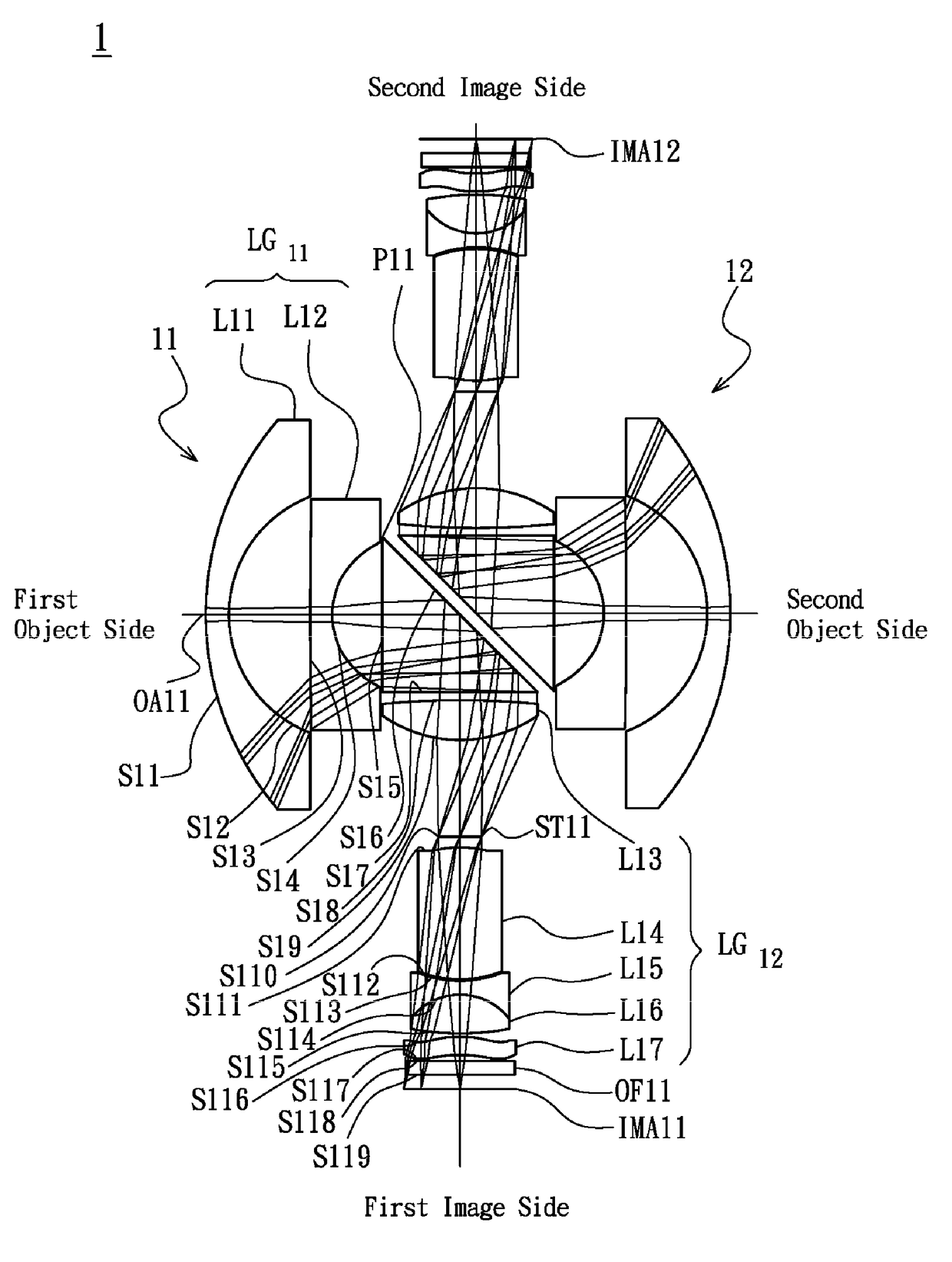
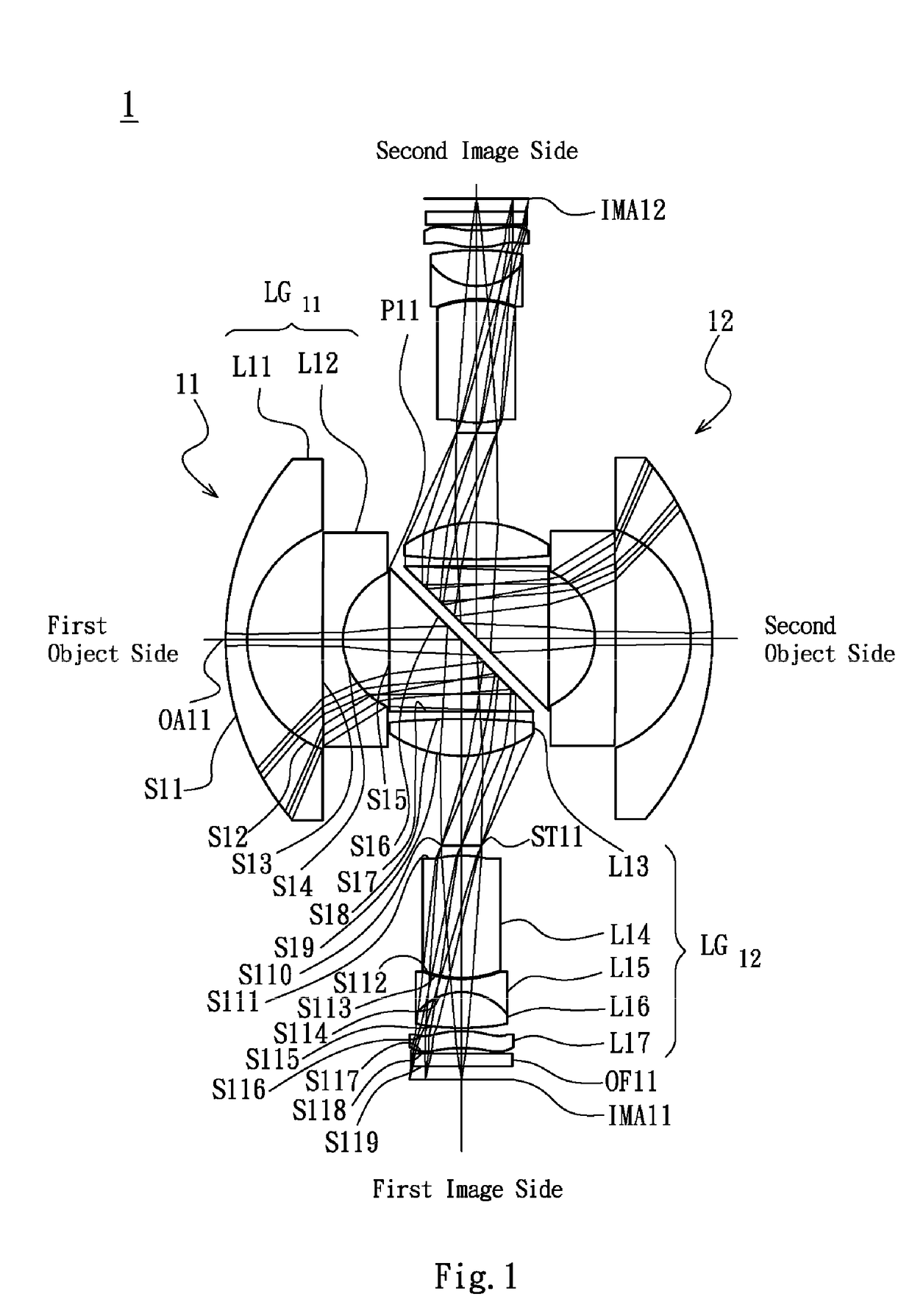
[0032]wherein TTL11 is an interval in mm from the object surface S11 of the first lens L11 to the first image plane IMA11 along the first optical axis OA11, θ11m is a half maximum field of view in degree for the first lens assembly 11, f11 is an effective focal length of the first lens L11, R112 is a radius of curvature of the image side surface S12 of the first lens L11, ER111 is an effective radius of the object side surface S11 of the first lens L11, f1f is an effective focal length of the first lens assembly 11, Vd13 is an Abbe number of the third lens L13 and Vd15 is an Abbe number of the fifth lens L15.
[0033]By the above design of the lenses, stop ST11 and the first prism P11, the first lens ass...
second embodiment
[0042]In order to maintain excellent optical performance of the panoramic lens assembly in accordance with the invention, the panoramic lens assembly 2 satisfies at least one of the following conditions:
0.2≦TTL21 / θ21m≦0.4 (5)
−4≦f21 / R212≦−0.067 (6)
4≦ER211 / f2f≦8 (7)
37≦Vd23−Vd25≦50 (8)
[0043]wherein TTL21 is an interval in mm from the object surface S21 of the first lens L21 to the first image plane IMA21 along the first optical axis OA21, θ21m is a half maximum field of view in degree for the first lens assembly 21, f21 is an effective focal length of the first lens L21, R212 is a radius of curvature of the image side surface S22 of the first lens L21, ER211 is an effective radius of the object side surface S21 of the first lens L21, f2f is an effective focal length of the first lens assembly 21, Vd23 is an Abbe number of the third lens L23 and Vd25 is an Abbe number of the fifth lens L25.
[0044]By the above design of the lenses, stop ST21 and the first prism P21, the first lens ass...
third embodiment
[0053]In order to maintain excellent optical performance of the panoramic lens assembly in accordance with the invention, the panoramic lens assembly 3 satisfies at least one of the following conditions:
0.2≦TTL31 / θ31m≦0.4 (9)
−4≦f31 / R312≦−0.067 (10)
4≦ER311 / f3f≦8 (11)
37≦Vd33−Vd35≦50 (12)
[0054]wherein TTL31 is an interval in mm from the object surface S31 of the first lens L31 to the first image plane IMA31 along the first optical axis OA31, θ31m is a half maximum field of view in degree for the first lens assembly 31, f31 is an effective focal length of the first lens L31, R312 is a radius of curvature of the image side surface S32 of the first lens L31, ER311 is an effective radius of the object side surface S31 of the first lens L31, f3f is an effective focal length of the first lens assembly 31, Vd33 is an Abbe number of the third lens L33 and Vd35 is an Abbe number of the fifth lens L35.
[0055]By the above design of the lenses, stop ST31 and the first prism P31, the first lens ...
PUM
 Abstract
Description
Claims
Application Information
 - R&D Engineer
- R&D Manager
- IP Professional
- Industry Leading Data Capabilities
- Powerful AI technology
- Patent DNA Extraction
Browse by: Latest US Patents, China's latest patents, Technical Efficacy Thesaurus, Application Domain, Technology Topic.
© 2024 PatSnap. All rights reserved.Legal|Privacy policy|Modern Slavery Act Transparency Statement|Sitemap