Hydrogen station

a technology for hydrogen stations and hydrogen gas, applied in the direction of electrochemical generators, container filling under pressure, discharging methods, etc., can solve the problems of increased transportation costs and assembly costs, difficult to secure a sufficient installation space, and difficulty in properly disposing of respective devices, so as to improve the degree of freedom of installation

Active Publication Date: 2017-11-16
KOBE STEEL LTD
View PDF2 Cites 9 Cited by
  • Summary
  • Abstract
  • Description
  • Claims
  • Application Information

AI Technical Summary

Benefits of technology

[0005]An object of the present invention is to provide a hydrogen statio

Problems solved by technology

However, there is a case where it is difficult to secure a sufficient installation space for installing the hydrogen station in a site where an existing facility exists.
Further, when various devices of the hydrogen station are assembled on site according to the installation space within the s

Method used


Image

  • Hydrogen station
  • Hydrogen station
  • Hydrogen station

Examples


Embodiment Construction

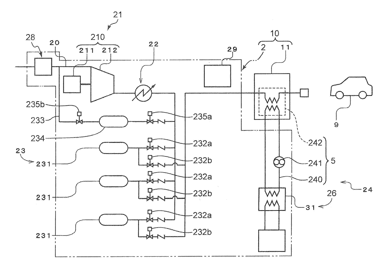
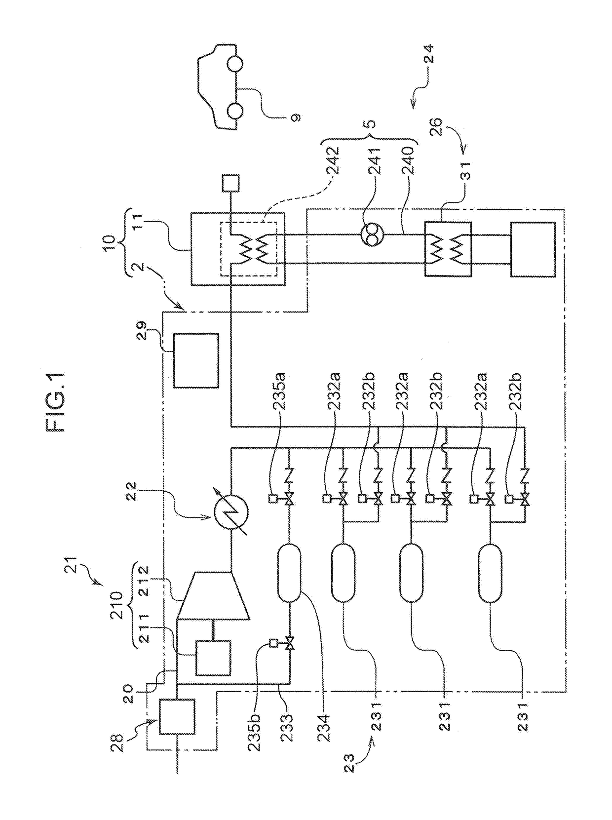
[0015]FIG. 1 is a diagram schematically showing a configuration of a hydrogen station 10 according to one embodiment of the present invention. The hydrogen station 10 includes a gas supply system 2 and a dispenser 11 serving as a filling facility

[0016]The gas supply system 2 supplies a hydrogen gas to the dispenser 11. The gas supply system 2 includes a gas flow path 20, a compressor unit 21, a pressure accumulator unit 23, a cooler unit 24, a receiving unit 28, and a control part 29. The receiving unit 28, the compressor unit 21, and the pressure accumulator unit 23 are disposed on the gas flow path 20. The hydrogen gas flows toward the dispenser 11 within the gas flow path 20. The control part 29 includes a control part body and a control part frame body for accommodating the control part body, the control part frame body being described later. The control part body controls the compressor unit 21, the pressure accumulator unit 23, and the cooler unit 24. In the following descript...


PUM


Abstract

[Object] To enable a gas supply system to be easily transported and to increase a degree of freedom when the gas supply system is installed. [Solution] A hydrogen station includes: a filling facility for filling a tank-mounted device with a gas; and a gas supply system for supplying the gas to the filling facility. The gas supply system includes: a compressor for compressing the gas; a compressor accommodating body for accommodating the compressor; a refrigerator for cooling the gas flowed into the filling facility or the gas just before being flowed into the filling facility, the refrigerator including an evaporation part, an expansion part, and a compression part; and a cooler accommodating body for accommodating the evaporation part, the expansion part, and the compression part. The compressor accommodating body and the cooler accommodating body are detachable from each other.

Description

TECHNICAL FIELD[0001]The present invention relates to a hydrogen station.BACKGROUND ART[0002]In recent years, a vehicle utilizing a hydrogen gas, such as a fuel cell vehicle or a hydrogen vehicle, (hereinafter, simply referred to as a “vehicle”) has been developed. Accordingly, a hydrogen station for filling a tank of the vehicle with the hydrogen gas has also been developed. For example, Patent Literature 1 discloses a mobile hydrogen station provided with a hydrogen producing device and a truck that is movable in a state in which the hydrogen producing device is loaded. This hydrogen station includes a compressor for compressing a hydrogen gas, a pressure accumulator for storing the hydrogen gas discharged from the compressor, a dispenser for filling a vehicle with the hydrogen gas supplied from the pressure accumulator, and the like. Since the hydrogen station described in Patent Literature 1 can be moved by a truck, even in a case where it is difficult to secure a site for insta...

Claims


Application Information

Patent Timeline
IPC IPC(8): F17C5/06
CPCF17C5/06F17C2221/012F17C2223/0123F17C2223/035F17C2227/0358F17C2250/01F17C2250/0626F17C2270/0581F17C5/007F17C2225/0123F17C2225/036F17C2227/0157F17C2227/0355F17C2265/065F17C2270/0139Y02P90/45F17C2201/0109F17C2201/035F17C2201/054F17C2205/0146F17C2205/0338F17C2227/0348F17C2270/0178F17C2270/0184Y02E60/32F17C13/025F17C2250/043
Inventor OKUNO, TAKASHITAKAGI, HITOSHINAGURA, KENJIWADA, DAISUKEUBA, TAKUROFUJISAWA, AKITOSHI
Owner KOBE STEEL LTD
Why Eureka
Try Eureka