
Light injector element

Inactive Publication Date: 2017-11-16
FRIEDERICH ALAIN LOUIS ANDRE +1
View PDF4 Cites 3 Cited by
  • Summary
  • Abstract
  • Description
  • Claims
  • Application Information

AI Technical Summary

Benefits of technology

The invention is a light injector that reduces energy loss and provides uniform energy flow in all directions. It consists of a body with a light source placed at one end. This design ensures that the light source emits energy that is not lost during the process of injection. The light injector also ensures that the energy is evenly distributed across the entire body, resulting in a more effective and consistent energy output.

Problems solved by technology

In this way, when an LED is installed for example in the ceiling of a room so as to emit light mainly to the vertical, it cannot illuminate at the horizontal, as a result reducing the quality of the lighting in the room.
Such lighting quality can pose problems of comfort for a user and needs multiplication of systems of lighting to rectify this defect.
However, such lighting elements have light outputs much weaker than LEDs and their light intensity fades over time.
Also, it often happens that such lighting elements scintillate, and can be particularly annoying for a user.
Now, the use of such mirrors introduces significant absorption of the energy flow reflected by the mirrors, which also causes a loss of useful energy, causes local heating of the injector element and finally heating of the biological liquid (bath).
However, apart from the fact that some of these mirrors can be industrially difficult to make, the absorption of the light flow they cause is considerable.
It is understood therefore that using such mirrors is particularly complicated and expensive in terms of power.

Method used


Image

  • Light injector element
  • Light injector element
  • Light injector element

Examples


Embodiment Construction

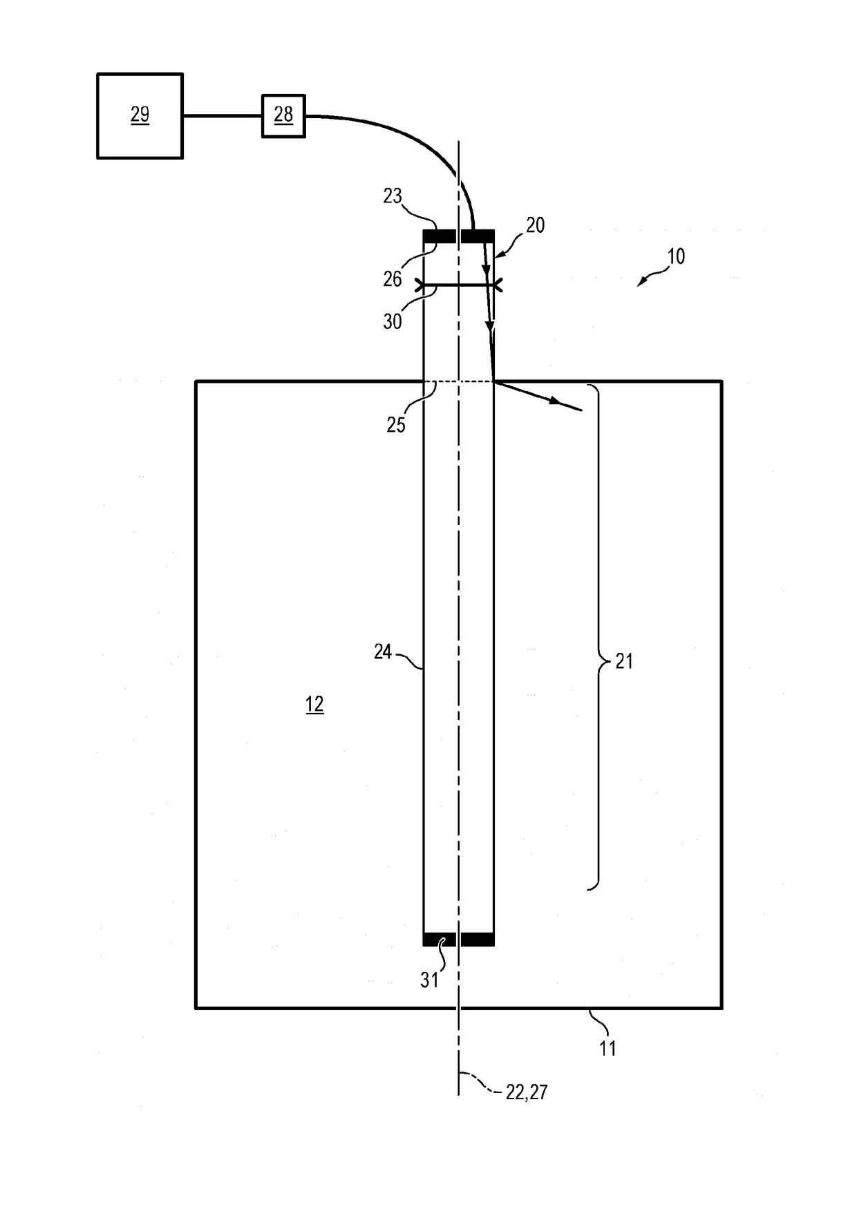
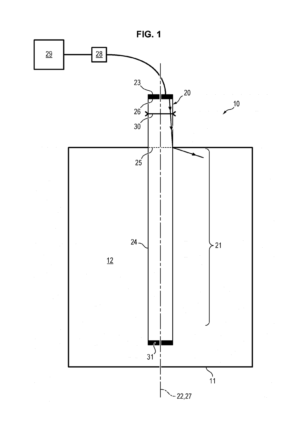
[0054]FIG. 1 shows a photobioreactor 10 intended for culture especially continuous culture of photosynthetic microorganisms, preferably of microalgae, according to an embodiment of the invention.

[0055]The photobioreactor 10 comprises at least one culture container 11 intended to contain the culture medium 12 of microorganisms, and at least one light injector element 20.

[0056]The light injector element 20 comprises a cylindrical body 21 extending according to a longitudinal axis 22. When used in a photobioreactor, the longitudinal axis 22 of the light injector element 20 coincides substantially with a vertical direction.

[0057]Cylinder means the volume generated by translation of a surface (forming a base) according to a direction orthogonal to the surface. For example, the body 21 can have the form of a cylinder of revolution (cylinder whereof the base is a disc) or a prism (cylinder whereof the base is a polygon). In particular, the body 21 can have the form of a rectangular paralle...


PUM


Abstract

The invention relates to a light injector element (20) comprising a body (21) extending according to a longitudinal axis (22), and a light source (23) placed facing an end (25) of the body (21), the light source (23) comprising a plurality of vertical-cavity surface-emitting laser (VCSEL) diodes, said plurality of diodes being arranged so as to form an emission surface (26) substantially perpendicular to the longitudinal axis (22) of the body (21).The invention also relates to a photobioreactor (10) comprising such a light injector element (20).

Description

TECHNICAL FIELD[0001]The present invention relates to the general field of lighting, and in particular that of lighting for intensive and continuous culture of photosynthetic microorganisms.PRIOR ART[0002]Many lighting elements are known from the prior art, such as for example luminescent or neon tubes, fluorescent tubes or light-emitting diodes (or LED).[0003]In particular, an LED has an energetic emission diagram according to a Lambertian profile, that is, in the form of a lobe. An LED emits maximum energy flow in a principal direction perpendicular to its emission surface, and this energy flow decreases moving away from this principal direction.[0004]Also, an LED has an emission cone whereof the solid angle is limited, typically by 90°. An LED therefore does not emit energy in directions having a strong inclination relative to the principal direction, especially beyond 45°. In this way, when an LED is installed for example in the ceiling of a room so as to emit light mainly to th...

Claims


Application Information

Patent Timeline
IPC IPC(8): H01S5/183H01S5/40C12M1/00
CPCH01S5/18344H01S5/4031C12M21/02C12M31/08G02B6/0008G02B6/0096G02B6/0068G02B6/0035G02B6/001G02B6/0006H01S3/10H01S5/183H01S5/20H01S2301/203
Inventor FRIEDERICH, ALAINRUIZ, GAELAFFI, MAHMOUD
Owner FRIEDERICH ALAIN LOUIS ANDRE
Learn More