Method of operating a long-term blood pressure measurement device

a measurement device technology, applied in the field of long-term blood pressure measurement devices, can solve the problems of unrecognized significant blood pressure changes, unnecessary stress on or unnecessarily irritating the wearer, and artifacts in pulse wave signals, and achieve the effect of high accuracy

Active Publication Date: 2017-11-23
MULLER & SEBASTIANI ELEKTRONIK
View PDF3 Cites 6 Cited by
  • Summary
  • Abstract
  • Description
  • Claims
  • Application Information

AI Technical Summary

Benefits of technology

[0007]It is an object of the invention to further develop the known long-term blood pressure measurement devices such that persons are disturbed as little as possible by the carrying out of the blood pressure measurements in long-term operation and such that simultaneously a high accuracy can be achieved in the determined blood pressure values.

Problems solved by technology

This has the result in a disadvantageous manner that significant blood pressure changes remain unrecognized when they occur in the time intervals between two measurements.
Furthermore, with regularly occurring measurements, unnecessary measurements are also carried out with unchanged blood pressure values, with these measurements then putting unnecessary stress on or unnecessarily irritating the persons wearing the device.
For example, the fact that the pulse wave signal is detected via a measurement sensor that has to be fixed to the finger or to the earlobe of a person, which is often irritating for the person, in particular in daily life, and which also frequently results in artifacts in the pulse wave signal due to movements of the person, is a disadvantage of this long-term blood pressure measurement device.
It is furthermore a disadvantage in the mentioned long-term blood pressure measurement device that the actual measurement of the blood pressure takes place via the pressure cuff, which for persons is associated with a high pressure on the upper arm, on the one hand, and with a comparatively loud noise of the compressed air source acting on the pressure cuff, on the other hand.
This has an irritating effect in everyday life and can also have the result that blood pressure values are falsified since some people are agitated by the blood pressure measurement they can clearly perceive, which then results in increased values and ultimately in values unrealistic for a normal everyday situation.
The calculation and calibration methods used here, however, disadvantageously frequently result in falsified blood pressure values.

Method used


Image

  • Method of operating a long-term blood pressure measurement device
  • Method of operating a long-term blood pressure measurement device

Examples


Embodiment Construction

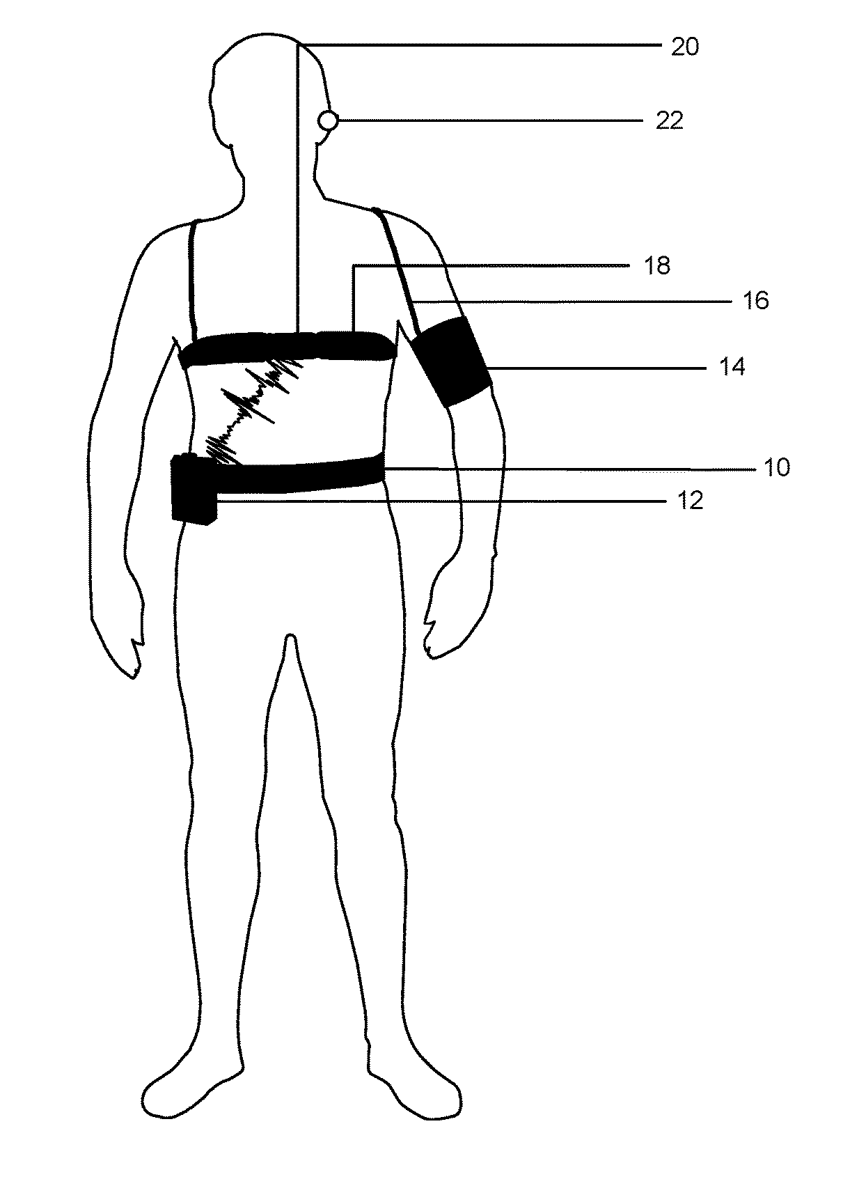
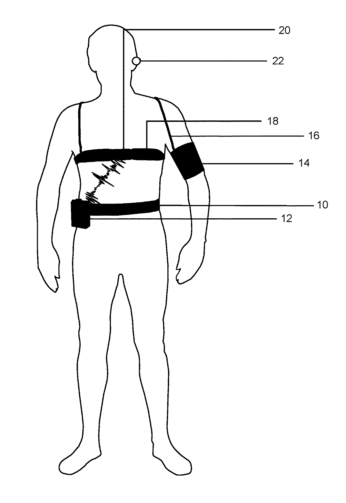
[0008]In accordance with the invention, this object is satisfied by the features of claim 1 and in particular in that, for calibration with an initially named long-term blood pressure measurement device, first[0009]a) a blood pressure value is determined from pressure cuff signals and in parallel therewith a pulse wave transit time is determined;[0010]b) a correlation between the blood pressure value and the pulse wave transit time corresponding thereto takes place in the form of a value pair in the memory; and[0011]c) in that the steps a) and b) are repeated for different blood pressure values at time intervals, whereby a correlation table is produced in the memory with a plurality of value pairs of a respective blood pressure value and a pulse wave transit time; and[0012]in that then, in long-term operation,[0013]d) pulse wave transit times are determined at consecutive points in time whose corresponding blood pressure values are each determined by means of the correlation table o...


PUM


Abstract

The invention relates to a method of operating a long-term blood pressure measurement device having a measurement sensor for detecting a pulse wave signal, having a measurement sensor for body current signals, having a pressure cuff for a non-invasive determination of the blood pressure, having a control and evaluation unit for determining blood pressure values, on the one hand from signals acquired by means of the pressure cuff (pressure cuff signals), and, on the other hand from a pulse wave transit time that is derived from body current signals and pulse wave signals, and having a memory for storing blood pressure values.

Description

CROSS-REFERENCES TO RELATED APPLICATIONS[0001]This application claims priority to German Patent Application No. 102016105684.7, filed Mar. 29, 2016, which is incorporated by reference herein.BACKGROUND OF THE INVENTION[0002]The present invention relates to a method of operating a long-term blood pressure measurement device having a measurement sensor for detecting a pulse wave signal, having a measurement sensor for body current signals, having a pressure cuff fora non-invasive determination of the blood pressure, having a control and evaluation unit for determining blood pressure values, on the one hand from signals acquired by means of the pressure cuff (pressure cuff signals), and, on the other hand from a pulse wave transit time that is derived from body current signals and pulse wave signals, and having a memory for storing blood pressure values.[0003]Such devices have been known for some time and are used e.g. in mobile form to be worn on the body of persons over comparatively...

Claims


Application Information

Patent Timeline
Patent Type & Authority Applications(United States)
IPC IPC(8): A61B5/021A61B5/022A61B5/0225A61B5/00
CPCA61B5/02141A61B5/02233A61B5/02255A61B2560/0223A61B5/6824A61B5/6826A61B5/6823A61B5/6815A61B5/022A61B5/11A61B5/02125A61B5/6817A61B5/282A61B5/333
Inventor ZIRNGIBL, CHRISTIAN
Owner MULLER & SEBASTIANI ELEKTRONIK
Why Eureka
Try Eureka